 |


Do not spin the bearing with compressed air because this will damage the bearing surfaces. 12 глава
|
|
|
|
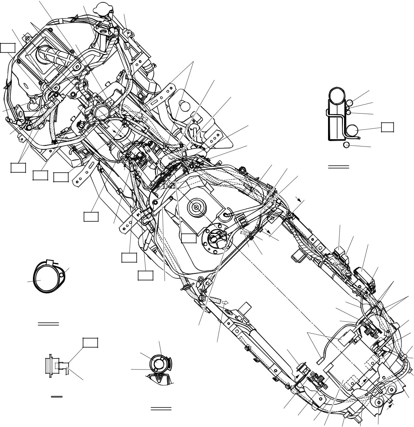
 CABLE ROUTING SPEC
Й Fasten the wire harness and seat lock cable to the frame with a plastic holder.
К Pass the wire harness, lead and cable the out-side of the frame bracket.
Ъ Install the starter relay to the mad guard.
Л Fasten the wire harness, positive battery lead and seat lock cable to the mad guard with a plastic holder.
П Route the positive battery lead through the under the seat lock cable.
Т Fasten the wire harness to the frame with a plas-tic holder.
У Connect the seat lock cable (gray) to the left seat lock.
Я Install the fuse box assembly to the storage box.
Ф Install the storage box light switch to the storage box.
Б To the rear brake caliper
| Й | К | ||||||
| Й И | Л | ||||||
| AH | |||||||
| М | |||||||
| I | |||||||
| H | |||||||
| Н | AI | ||||||
| G | О | ||||||
| AG | D | П 4 | A-A | ||||
| AF | AE | D | |||||
| A | |||||||
| AD | A | ||||||
| F | |||||||
| 9 0 | |||||||
| AA | 6 Р | ||||||
| AC | С | Т | |||||
| L | |||||||
| M | AB | E | Ф | ||||
| Х | |||||||
| У | |||||||
| D-D | |||||||
| A | |||||||
| D | Я | Ц | |||||
| AJ | I | А | Ч | ||||
| Б | |||||||
| J | |||||||
| Ш | |||||||
| C | Щ | ||||||
| K | |||||||
| C | B | ||||||
| B-B | |||||||
| Ъ | |||||||
| A | B | ||||||
| C Ю B Э Ь Ы | |||||||
| 2 - 50 |

|
|
|
CABLE ROUTING SPEC

A A
A B
A C
A D
To the storage box light switch on the seat hinge.
Fasten the fuel injector lead (#1/#2), intake air pressure sensor lead to the frame with a plas-tic holder.
Route the intake air pressure sensor lead over the fuel hose.
Bundle the fuel injector lead (#2) to the frame with a plastic band softly (the band possible to turn), face the end of the plastic band to the inside of the frame.
A E 10 ~ 15 mm (0.39 ~ 0.59 in)
A F Route the wire harness through the wire guide. A G Pass the speed sensor lead under the stay 1 and cross pipe, and then over the brake hose
guide.
A H Place the speed sensor lead between the ribs of the air filter case.
A I Pass the wire harness over the wire guide.
A J Connect the storage box light lead connectors to the storage box light with the leads routed downward.
| Й | К | ||||||
| Й И | Л | ||||||
| AH | |||||||
| М | |||||||
| I | |||||||
| H | |||||||
| Н | AI | ||||||
| G | О | ||||||
| AG | D | П 4 | A-A | ||||
| AF | AE | D | |||||
| A | |||||||
| AD | A | ||||||
| F | |||||||
| 9 0 | |||||||
| AA | 6 Р | ||||||
| AC | С | Т | |||||
| L | |||||||
| M | AB | E | Ф | ||||
| Х | |||||||
| У | |||||||
| D-D | |||||||
| A | |||||||
| D | Я | Ц | |||||
| AJ | I | А | Ч | ||||
| Б | |||||||
| J | |||||||
| Ш | |||||||
| C | Щ | ||||||
| K | |||||||
| C | B | ||||||
| B-B | |||||||
| Ъ | |||||||
| A | B | ||||||
| C Ю B Э Ь Ы | |||||||
| 2 - 51 |
|
|
|
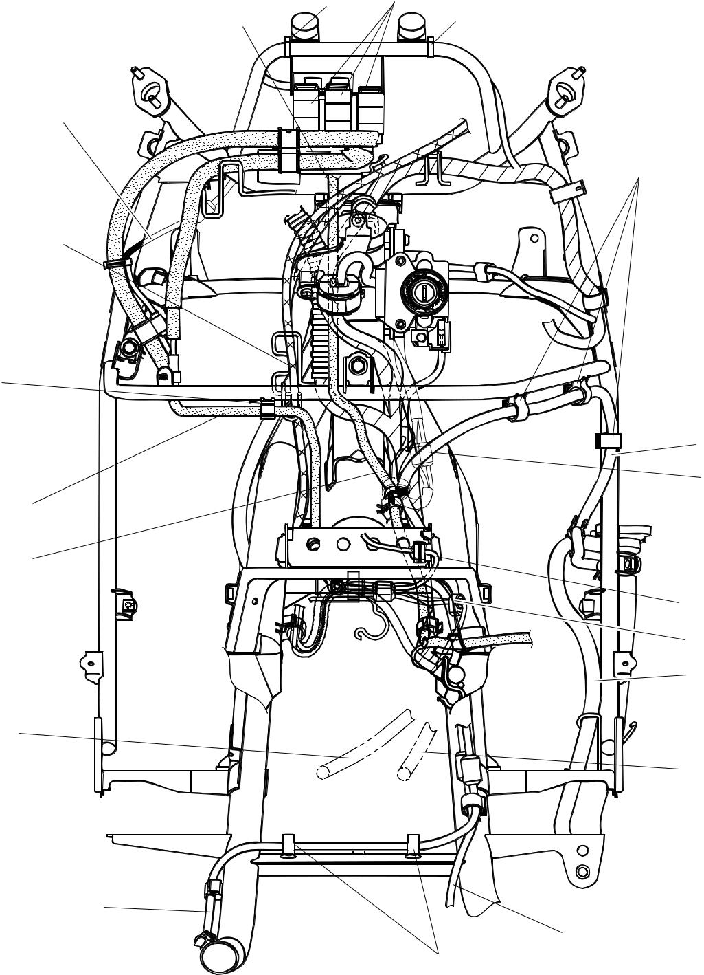
| CABLE ROUTING | SPEC | ||||
| 1 Cooling system air bleed hose | |||||
| И Pass the rear brake lock lever cable on the front | |||||
| 2 Storage box light switch lead | side of throttle cable. | ||||
| 3 Coolant reservoir hose | Й Position of clamp. | ||||
| 4 Spark plug lead #2 | К Position the relay straighten. | ||||
| 5 Radiator fan motor lead | Л Fasten the cooling system air bleed hose to the | ||||
| 6 Sidestand switch lead | stay 1 with a plastic holder. | ||||
| 7 Spark plug lead #1 | М The main switch lead couplers should not pro- | ||||
| 8 Rear brake lock lever cable | trude to the outside of the frame. | ||||
| 9 Rear brake hose | Н Fasten the fuel injector leads with the plastic | ||||
| 0 Speed sensor lead | holder. |

| Й | К |
| И | Й |
| Л | |
| Р | |
| П | |
| М | |
| Н | |
| О | |
| 2 - 52 |


CABLE ROUTING SPEC
Х Fasten the sidestand switch lead to the frame with a plastic holder.
Ч Fasten the rear brake hose to the stay 1 with a plastic holder.
Ш Route the throttle cable through the cable holder.
| Й | К |
| И | Й |
| Л | |
| Р | |
| П | |
| М | |
| Н | |
| О | |
| 2 - 53 |
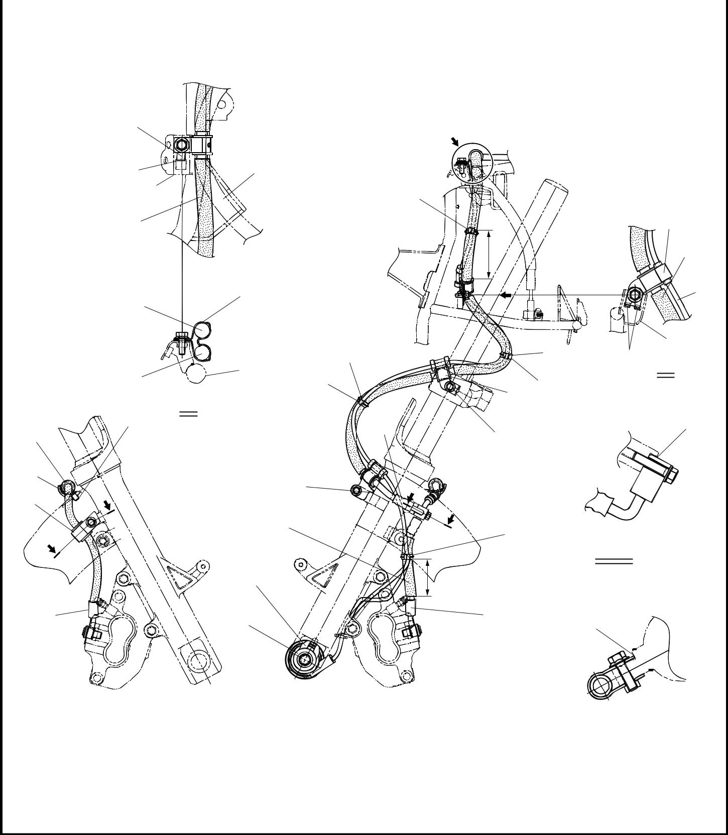
| CABLE ROUTING | SPEC | ||||
| 1 Brake hose holder 1 | |||||
| И Fasten the speed sensor lead along the inside of | |||||
| 2 Front brake hose | the brake hose. | ||||
| 3 Speed sensor | Й 50 ~ 60 mm (1.97 ~ 2.36 in) | ||||
| 4 Plastic holder | К Turn the handlebar completely to the right, and | ||||
| 5 Brake hose holder 2 | then fasten the brake hose and speed sensor | ||||
| 6 Speed sensor lead | lead together with the plastic holder. | ||||
| 7 Stay1 | Л Install the stopper to lower bracket projection. | ||||
| 8 Brake hose holder 3 | М Fasten the speed sensor lead along the outside | ||||
| 9 Rear brake hose 1 | of the brake hose. | ||||
| Н 30 ~ 40 mm (1.18 ~ 1.57 in) |

| A | |||||||
| Ц | |||||||
| И | |||||||
| Й | |||||||
| Ч | B | ||||||
| Т | К | Ц | |||||
| B | |||||||
| М | |||||||
| И | |||||||
| A | |||||||
| Ф | У | С | Ш | ||||
| Л | |||||||
| Р | C | ||||||
| D | |||||||
| C | |||||||
| D | М | ||||||
| C-C | |||||||
| П | Н | ||||||
| Х | О | Щ | |||||
| Right side | Left side | D-D | |||||
| 2 - 54 |

|
|
|
CABLE ROUTING SPEC
T Make sure that brake pipe touches the projec-tion.
Й Make sure that the slot in the speed sensor fits stopper on the outer tube.
К Make sure that the stopper touches the outer tube stay.
Л Pass the speed sensor lead between the brake hose and front fork.
Т Fasten the speed sensor lead to the center of brake hose holder.
У Install the hose holder to the innermost securely.

М Engage the hose holder rib more than 3 notch. Face the hose holder projection to the back.
Н Make sure that the white paint on the brake hose faces to back (right side only).
Ц Install the stopper to the stay 1.
О Fasten the front brake hose and rear brake hose with a hose holder.
П Make sure that the brake hose joint touches the projection of the outer tube.
Р Make sure that the brake hose holder touches the projection of the outer tube.
| A | |||||||
| Ц | |||||||
| И | |||||||
| Й | |||||||
| Ч | B | ||||||
| Т | К | Ц | |||||
| B | |||||||
| М | |||||||
| И | |||||||
| A | |||||||
| Ф | У | С | Ш | ||||
| Л | |||||||
| Р | C | ||||||
| D | |||||||
| C | |||||||
| D | М | ||||||
| C-C | |||||||
| П | Н | ||||||
| Х | О | Щ | |||||
| Right side | Left side | D-D | |||||
| 2 - 55 |
|
|
|
