 |


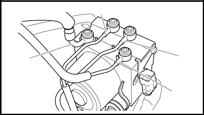
Installing the hydraulic unit
|
|
|
|
Proceed in the reverse order of disassembly.
Pay attention to the following items.
| 1. | Install: | ||
| • | hydraulic unit | T.R. | 16 Nm (1.6 m · kg, 11 ft · lb) |

NOTE:

• When tightening the hydraulic unit nuts, first temporarily tighten the front nuts, and then tighten the rear nut and the front nuts to specification in the order given.
• Do not allow any foreign materials to enter the hydraulic unit or the brake hoses when installing the hydraulic unit.

CAUTION:

| Do not remove the rubber plugs or bolts | ||
| (M10Ч1.25) installed in the union bolt | ||
| holes before installing the hydraulic unit. | ||
| 2. Remove: | ||
| • rubber plugs or bolts (M10 Ч 1.25) | ||
| 3. Install: | ||
| • copper washers New | ||
| • brake hose 1 (to the rear brake caliper) | ||
| • brake hose 2 (from the rear brake master | ||
| cylinder) |
К • brake hose 3 (to the front brake caliper)
brake hose 4 (from the front brake master cylinder)
union bolts  T. 30 Nm (3.0 m · kg, 22 ft · lb)
 R.
R.

 WARNING

The brake hoses to the front and rear brake calipers can be distinguished by the rubber at the end of each hose. Be sure to connect each brake hose to the correct union bolt hole.

CAUTION:

To route the front and rear brake hoses, refer to “CABLE ROUTING” in chapter 2.
4 - 65
 FRONT AND REAR BRAKES CHAS
Л Fill:
brake master cylinder reservoirs

Recommended brake fluid
DOT 4
М Bleed the brake system.
М Check the operation of the hydraulic unit according to the brake levers response. (Refer to “[D-6-3-1] Hydraulic unit operation test 1”.)
CAUTION:
Always check the operation of the hydrau-lic unit according to the brake levers response.
4 - 66
HANDLEBAR CHAS
HANDLEBAR

| Order | Job/Part | Q’ty | Remarks | |||
| Removing the handlebar | Remove the parts in the order listed. | |||||
| Upper handlebar cover | ||||||
| Band | ||||||
| Grip end | ||||||
| Front brake light switch connector | Disconnect. | |||||
| Right handlebar switch | ||||||
| Throttle cable | Disconnect. | |||||
| Throttle grip | Refer to “INSTALLING | |||||
| Front brake master cylinder holder | THE HANDLEBAR”. | |||||
| Front brake master cylinder | ||||||
| Rear brake light switch connector | Disconnect. | |||||
|
|
|
4 - 67
HANDLEBAR CHAS
| Order | Job/Part | Q’ty | Remarks | |||||
| Parking brake lever/holder | 1/1 | |||||||
| Rear brake lock lever cable | Disconnect. | |||||||
| Left handlebar switch | Refer to “INSTALLING | |||||||
| THE HANDLEBAR”. | ||||||||
| Rear brake master cylinder holder | ||||||||
| Rear brake master cylinder | ||||||||
| Handlebar grip | Refer to “REMOVING THE HANDLE- | |||||||
| BAR” and “INSTALLING THE HANDLE- | ||||||||
| BAR”. | ||||||||
| Upper handlebar holder | Refer to “INSTALLING THE HANDLE- | |||||||
| Handlebar | BAR”. | |||||||
| Lower handlebar cover | ||||||||
| For installation, reverse the removal pro- | ||||||||
| cedure. | ||||||||
4 - 68
HANDLEBAR CHAS
EAS00666
REMOVING THE HANDLEBAR
1. Stand the scooter on a level surface.
 WARNING

Securely support the scooter so that there is no danger of it falling over.
Н Remove:
handlebar grip 1

NOTE:
Blow compressed air between the handlebar and the handlebar grip, and gradually push the grip off the handlebar.
CHECKING THE HANDLEBAR
О Check:
handlebar
Bends/cracks/damage → Replace.

 WARNING
Do not attempt to straighten a bent handle-bar as this may dangerously weaken it.
EAS00671
INSTALLING THE HANDLEBAR
1. Stand the scooter on a level surface.
WARNING
Securely support the scooter so that there is no danger of it falling over.
4 - 69

b 1

UP
a
HANDLEBAR CHAS
П  Install:
handlebar 1
handlebar upper holders 2
| T.R. | 23 Nm (2.3 m · kg, 17 ft · lb) |

 WARNING
First, tighten the bolts on the front side of the handlebar holder, then on the rear side.
NOTE:
РThe upper handlebar holders should be installed with the arrow marks a facing for-ward И.
|
|
|
РAlign the match mark b on the handlebar with the upper surface of the lower handlebar holder.
С Install:
handlebar grip
grip end
▼▼▼▼▼▼▼▼▼▼▼ ▼▼▼▼▼▼▼▼▼ ▼▼▼▼▼▼▼▼▼▼▼▼
У Apply a thin coat of rubber adhesive onto the left end of the handlebar.
У Slide the handlebar grip over the left end of the handlebar.
У Wipe off any excess rubber adhesive with a clean rag.
WARNING
|
|
|
