 |


Intake air temperature sensor resistance
|
|
|
|
2.21 ~ 2.69 k Ω at 20 °C (68 °F)

| WARNING | ||||||
| • Handle the intake air temperature sensor | ||||||
| with special care. | ||||||
| • Never subject the intake air temperature sen- | ||||||
| sor to strong shocks. If the intake air temper- | ||||||
| ature sensor is dropped, replace it. | ||||||
| 4. Is the intake air temperature sensor OK? | ||||||
| Open or short circuit in wiring har- | Repair or replace if there is an open or short circuit. | |||||
| ness. | Between sensor coupler and ECU (engine) coupler | |||||
| black/blue – black/blue | ||||||
| brown/white – brown/white | ||||||
| Connected condition of connector | If there is a malfunction, repair it and connect it | |||||
| Inspect the coupler for any pins | securely. | |||||
| that may have pulled out. | Intake air temperature sensor coupler | |||||
| Check the locking condition of the | Main wiring harness ECU (engine) coupler | |||||
| coupler. |
7 - 17
| FUEL INJECTION SYSTEM | FI | ||||||||
| Fault code No. | Symptom No normal signal is received from the O2 sensor. | ||||||||
| Used diagnostic code No. -- | |||||||||
| Order | Inspection operation item and | Operation item and countermeasure | Reinstatement | ||||||
| probable cause | method | ||||||||
| Installed state of O2 sensor | Check the installed area for looseness or pinching. | As the returning | |||||||
| method start | |||||||||
| Connected state of connector | Check the coupler for any pins that may have pulled | ||||||||
| method, start and | |||||||||
| O2 sensor coupler | out. Check the locking condition of the coupler. If | ||||||||
| warm up the | |||||||||
| Main wiring harness ECU | there is a malfunction, repair it and connect it | ||||||||
| engine until the | |||||||||
| (engine) coupler | securely. | ||||||||
| coolant tempera- | |||||||||
| Open or short circuit in wiring har- | Repair or replace if there is an open or short circuit. | ture rises over | |||||||
| ness | Between O2 sensor coupler and ECU (engine) cou- | 60 °C (140 °F). | |||||||
| pler | Then, maintain the | ||||||||
| black/blue – black/blue | engine speed at | ||||||||
| gray/green – gray/green | 2,000 r/min to | ||||||||
| red/blue – red/blue | 3,000 r/min until | ||||||||
| black – black | the warning light | ||||||||
| goes off. When the | |||||||||
| Check fuel pressure | Refer to “CHECKING THE FUEL PUMP OPERA- | ||||||||
| warning light goes | |||||||||
| TION”. | |||||||||
| off, the reset oper- | |||||||||
| Defective O2 sensor | Replace if defective. | ation is finished. | |||||||

|
|
|
7 - 18
| FUEL INJECTION SYSTEM | FI | |||||||||||||
| Fault code No. | Symptom | The scooter has overturned. | ||||||||||||
| Used diagnostic code No. 08 (lean angle cut-off switch) | ||||||||||||||
| Order | Inspection operation item and | Operation item and countermeasure | Reinstatement | |||||||||||
| probable cause | method | |||||||||||||
| Defective lean angle cut-off switch | Replace if defective. | Reinstated by turn- | ||||||||||||
| 1. | Remove the lean angle cut-off switch from the | ing the main switch | ||||||||||||
| scooter. | ON (however, the | |||||||||||||
| 2. | Connect the lean angle cut-off switch coupler to | engine cannot be | ||||||||||||
| the wire harness. | restarted unless | |||||||||||||
| 3. | Connect the pocket tester (DC 20 V) to the lean | the main switch is | ||||||||||||
| angle cut-off switch coupler as shown. | first turned OFF). | |||||||||||||
| Positive tester probe→blue1 | ||||||||||||||
| Negative tester probe→yellow/green2 | ||||||||||||||
| 4. When turn the lean angle cut-off switch approx. | ||||||||||||||
| 45°, the voltage reading change from 0.9 V to | ||||||||||||||
| 4.1 V. | ||||||||||||||
| 5. Is the emergency stop switch OK? | ||||||||||||||
| The scooter has overturned. | Raise the scooter upright. | |||||||||||||
| Installed condition of the lean | Check the installed area for looseness or pinching. | |||||||||||||
| angle cut-off switch | ||||||||||||||
| Connected condition of connector | If there is a malfunction, repair it and connect it | |||||||||||||
| Inspect the coupler for any pins | securely. | |||||||||||||
| that may have pulled out. | Lean angle cut-off switch coupler | |||||||||||||
| Check the locking condition of the | Main wiring harness ECU (engine) coupler | |||||||||||||
| coupler. | ||||||||||||||
| Fault code No. | Symptom | Malfunction detected in the primary lead of the ignition coil. | ||||||||||||
| Used diagnostic code No. 30 (ignition coil) | ||||||||||||||
| Order | Inspection operation item and | Operation item and countermeasure | Reinstatement | |||||||||||
| probable cause | method | |||||||||||||
| Defective ignition coil (test the pri- | Replace if defective. | Reinstated by | ||||||||||||
| mary and secondary coils for conti- | Refer to “IGNITION SYSTEM” in chapter 8. | starting the engine | ||||||||||||
| nuity) | and operating it at | |||||||||||||
| idle. | ||||||||||||||
| Open or short circuit in lead. | Repair or replace if there is an open or short circuit. | |||||||||||||
| In case of multiple | ||||||||||||||
| Between ignition coil coupler and ECU (engine) cou- | ||||||||||||||
| cylinder open or | ||||||||||||||
| pler/ main harness | short circuit in lead, | |||||||||||||
| orange – orange | ||||||||||||||
| make sure to turn | ||||||||||||||
| red/black – red/black | ||||||||||||||
| ON and OFF the | ||||||||||||||
| Connected condition of connector | If there is a malfunction, repair it and connect it | main switch after | ||||||||||||
| Inspect the coupler for any pins | securely. | each time of crank- | ||||||||||||
| that may have pulled out. | Ignition coil primary side coupler – orange | ing. | ||||||||||||
| Check the locking condition of the | Main wiring harness ECU (engine) coupler | |||||||||||||
| coupler. | ||||||||||||||
| 7 - 19 |

|
|
|
|
|
|
| FUEL INJECTION SYSTEM | FI | |||||||||
| Fault code No. | Symptom | Engine idling speed is too high. | ||||||||
| Used diagnostic code No. 01 (throttle position sensor) | ||||||||||
| Order | Inspection operation item and | Operation item and countermeasure | Reinstatement | |||||||
| probable cause | method | |||||||||
| Stuck FID valve detected. | Inspect the throttle body. | Reinstated by | ||||||||
| Replace if defective. | starting the engine | |||||||||
| Refer to “THROTTLE BODY”. | and operating it at | |||||||||
| idle for about 5 | ||||||||||
| Defective throttle fully closed. | Inspect the throttle body. | |||||||||
| minutes. Do not | ||||||||||
| Replace if defective. | ||||||||||
| turn the throttle | ||||||||||
| Refer to “THROTTLE BODY”. | ||||||||||
| grip. | ||||||||||
| Fault code No. | Symptom | Open or short circuit detected in the lean angle cut-off switch. | ||||||||
| Used diagnostic code No. 08 (lean angle cut-off switch) | ||||||||||
| Order | Inspection operation item and | Operation item and countermeasure | Reinstatement | |||||||
| probable cause | method | |||||||||
| Defective lean angle cut-off switch | Replace if defective. | Reinstated by turn- | ||||||||
| Refer to “Fault code No. 30”. | ing the main switch | |||||||||
| ON. | ||||||||||
| Open or short circuit in wiring har- | Repair or replace if there is an open or short circuit. | |||||||||
| ness. | Between switch coupler and ECU (engine) coupler | |||||||||
| black/blue – black/blue | ||||||||||
| yellow/green – yellow/green | ||||||||||
| blue – blue | ||||||||||
| Connected condition of connector | If there is a malfunction, repair it and connect it | |||||||||
| Inspect the coupler for any pins | securely. | |||||||||
| that may have pulled out. | Lean angle cut-off switch coupler | |||||||||
| Check the locking condition of the | Main wiring harness ECU (engine) coupler | |||||||||
| coupler. | ||||||||||
|
|
|
7 - 20
| FUEL INJECTION SYSTEM | FI | ||||||||||||||||||||||||||||
| Fault code No. | Symptom The ECU (engine) is unable to monitor the battery voltage. | ||||||||||||||||||||||||||||
| Used diagnostic code No. 09 (fuel system voltage) | |||||||||||||||||||||||||||||
| Order | Inspection operation item and | Operation item and countermeasure | Reinstatement | ||||||||||||||||||||||||||
| probable cause | method | ||||||||||||||||||||||||||||
| Malfunction in ECU (engine) | Fuel injection system relay is on. | Reinstated by | |||||||||||||||||||||||||||
| starting the engine | |||||||||||||||||||||||||||||
| Open or short circuit in the wiring | Repair or replace if there is an open or short circuit. | ||||||||||||||||||||||||||||
| and operating it at | |||||||||||||||||||||||||||||
| harness. | Between starting circuit cut-off relay (fuel injection | ||||||||||||||||||||||||||||
| idle. | |||||||||||||||||||||||||||||
| system relay), fuel pump, fuel injector (#1, #2) | |||||||||||||||||||||||||||||
| red/blue – red/blue | |||||||||||||||||||||||||||||
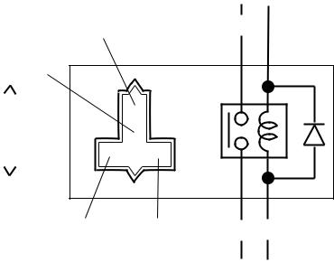
| Malfunction or open circuit in fuel | Replace if defective. | ||||||||||||||||||||||||||||
| injection system relay | 1. Disconnect the fuel injection system relay from | ||||||||||||||||||||||||||||
| the wire harness. | |||||||||||||||||||||||||||||
| 2. Connect the pocket tester (Ω Ч 1) and battery | |||||||||||||||||||||||||||||
| (12 V) to the fuel injection system relay terminals | |||||||||||||||||||||||||||||
| as shown. | |||||||||||||||||||||||||||||
| Positive battery terminal→red/black1 | |||||||||||||||||||||||||||||
| Negative battery terminal→blue/yellow2 | |||||||||||||||||||||||||||||
| Positive tester probe→red/blue3 | |||||||||||||||||||||||||||||
| Negative tester probe→red/blue4 | |||||||||||||||||||||||||||||
| R/L | |||||||||||||||||||||||||||||
| R/B | |||||||||||||||||||||||||||||
| R/L | |||||||||||||||||||||||||||||
| R/L | |||||||||||||||||||||||||||||
| R/B | L/Y | ||||||||||||||||||||||||||||
| R/L | L/Y | ||||||||||||||||||||||||||||
| 3. Does the fuel injection system relay have conti- | |||||||||||||||||||||||||||||
| nuity between red/blue and red/blue? | |||||||||||||||||||||||||||||
| Connected condition of connector | If there is a malfunction, repair it and connect it | ||||||||||||||||||||||||||||
| Inspect the coupler for any pins | securely. | ||||||||||||||||||||||||||||
| that may have pulled out. | Fuel injection system relay coupler | ||||||||||||||||||||||||||||
| Check the locking condition of the | ECU (engine) coupler | ||||||||||||||||||||||||||||
| coupler. | |||||||||||||||||||||||||||||
|
|
|
7 - 21
| FUEL INJECTION SYSTEM | FI | ||||||||||
| Fault code No. | Symptom | Error is detected while reading or writing on EEPROM (CO adjustment value). | |||||||||
| Used diagnostic No. 60 (EEPROM improper cylinder indication) | |||||||||||
| Order | Inspection operation item and | Operation item and countermeasure | Reinstatement | ||||||||
| probable cause | method | ||||||||||
| Malfunction in ECU (engine) | Execute diagnostic code 60 | Reinstated by turn- | |||||||||
| • Check the faulty cylinder. (If there are multiple | ing the main switch | ||||||||||
| cylinders, the number of the faulty cylinders | ON. | ||||||||||
| appear alternately at 2-second intervals.) | |||||||||||
| • | Readjust the CO of the displayed cylinder. | ||||||||||
| Refer to “ADJUSTING THE EXHAUST GAS | |||||||||||
| VOLUME” in chapter 3. Replace ECU (engine) | |||||||||||
| if defective. | |||||||||||
| Fault code No. | Symptom | Power supply to the fuel pump relay is not normal. | |||||||||
| Used diagnostic code No. – – | |||||||||||
| Order | Inspection operation item and | Operation item and countermeasure | Reinstatement | ||||||||
| probable cause | method | ||||||||||
| Faulty battery | Replace or change the battery | Reinstated by | |||||||||
| Refer to “CHECKING AND CHARGING THE BAT- | starting the engine | ||||||||||
| TERY” in chapter 3. | and operating it at | ||||||||||
| idle. | |||||||||||
| Open or short circuit in wiring har- | Repair or replace if there is an open circuit. | ||||||||||
| ness. | • | Between battery and main switch | |||||||||
| red – red | |||||||||||
| • | Between main switch and fuse (ignition) | ||||||||||
| brown/blue – brown/blue | |||||||||||
| • | Between fuse (ignition) and ECU (engine) | ||||||||||
| red/white – red/white | |||||||||||
| Connected condition of connector | If there is a malfunction, repair it and connect it | ||||||||||
| Inspect the coupler for any pins | securely. | ||||||||||
| that may have pulled out. | ECU (engine) coupler | ||||||||||
| Check the locking condition of the | |||||||||||
| coupler. | |||||||||||
|
|
|
Воспользуйтесь поиском по сайту:

©2015 - 2026 megalektsii.ru Все авторские права принадлежат авторам лекционных материалов. Обратная связь с нами...