 |


ECU (engine) self-diagnostic function
|
|
|
|
The ECU (engine) is equipped with a self-diagnostic function in order to ensure that the fuel injec-tion system is operating normally. If this function detects a malfunction in the system, it immediately operates the engine under substitute characteristics and illuminates the engine trouble warning light to alert the rider that a malfunction has occurred in the system. Once a malfunction has been detected, a fault code is stored in the memory of the ECU (engine).
DD To inform the rider that the fuel injection system is not functioning, the engine trouble warning light flashes when the start switch is being pushed to start the engine.
EE If a malfunction is detected in the system by the self-diagnostic function, the ECU (engine) pro-vides an appropriate substitute characteristic operation, and alerts the rider of the detected mal-function by illuminating the engine trouble warning light.
FF After the engine has been stopped, the lowest fault code number appears on the clock LCD. Once a fault code has been displayed, it remains stored in the memory of the ECU (engine) until it is deleted.
EAS00900
Engine trouble warning light indication and FI system operation
| Warning light | ECU (engine) opera- | FI operation | Vehicle operation | |
| indication | tion | |||
| Flashing* | Warning provided | Operation stopped | Can not be operated | |
| when unable to start | ||||
| engine | ||||
| Remains ON | Malfunction detected | Operated with substi- | Can or cannot be | |
| tute characteristics in | operated depending | |||
| accordance with the | on the fault code | |||
| description of the mal- | ||||
| function. | ||||
Й The warning light flashes when any one of the conditions listed below is present and the start switch is pushed:
| 12: Crankshaft position sensor | 41: Lean angle cut-off switch | |
| (open or short-circuit) | ||
| 19: Sidestand switch | ||
| 50: ECU (engine) internal malfunction | ||
| (open circuit in the wire to the ECU | ||
| (faulty ECU (engine) memory) | ||
| (engine)) | ||
| 30: Lean angle cut-off switch | ||
| (latch up detected) |
7 - 3
| FUEL INJECTION SYSTEM | FI | |||

EAS00901
Checking for a defective engine trouble warning light bulb
The engine trouble warning light comes on for 1.4 seconds after the main switch has been turned to “ON” and when the start switch is being pushed. If the warning light does not come on under these conditions, the warning light bulb may be defective.
|
|
|
Main switch Main switch
OFF ON
Engine trouble Light Light on for 1.4 Light
warning light off seconds off
Initialize
EAS00902
ALTERNATE INSTRUCTIONS OPERATION CONTROL (FAIL-SAFE ACTION)
If the ECU (engine) detects an abnormal signal from a sensor while the vehicle is being driven, the ECU (engine) illuminates the engine trouble warning light and provides the engine with alternate operating instructions that are appropriate for the type of malfunction.
When an abnormal signal is received from a sensor, the ECU (engine) processes the specified val-ues that are programmed for each sensor in order to provide the engine with alternate operating instructions that enable the engine to continue to operate or stop operating, depending on the condi-tions.
The ECU (engine) takes fail-safe actions in two ways: one in which the sensor output is set to a pre-scribed value, and the other in which the ECU (engine) directly operates an actuator. Details on the fail-safe actions are given in the table below.
EAS00903
FAIL-SAFE ACTION TABLE
| Fault | Item | Symptom | Fail-safe action | Engine start- | Vehicle drive- | |
| code No. | ability | ability | ||||
| Crankshaft position | No normal signals are | -- | ||||
| sensor | received from the crankshaft | Unable | Unable | |||
| position sensor. | ||||||
| Intake air pressure | Intake air pressure sensor- | Fixes the intake air pressure | ||||
| sensor (open or short | open or short circuit detected. | to 101.12 kPa | Able | Able | ||
| circuit) (pipe system) | Faulty intake air pressure sen- | (1.01 kgf/cm2, 14.4 psi). | ||||
| sor system. | ||||||
| Throttle position sensor | Throttle position sensor-open | Fixes the throttle position | ||||
| (open or short circuit) | or short circuit detected. | sensor to fully open. | Able | Able | ||
| (stuck) | ||||||
| Sidestand switch (open | Open circuit is detected in the | -- (No start) | ||||
| circuit in wire to ECU | input line from the sidestand | Unable | Unable | |||
| (engine)) | switch to the ECU (engine). | |||||
| Coolant temperature | Coolant temperature sensor- | Fixes the coolant tempera- | Able | Able | ||
| sensor | open or short circuit detected. | ture to 80 °C (176 °F). | ||||
| Intake temperature | Intake temperature sensor- | Fixes the intake tempera- | Able | Able | ||
| sensor | open or short circuit detected. | ture to 20 °C (68 °F). | ||||
| O2 sensor (inactive) | No normal signals are | -- | Able | Able | ||
| received from the O2 sensor. | ||||||
| Faulty ignition | Open circuit detected in the | -- | ||||
| primary lead of the ignition | Unable | Unable | ||||
| coil. | ||||||
|
|
|
7 - 4
| FUEL INJECTION SYSTEM | FI | |||||||||
| Fault | Item | Symptom | Fail-safe action | Engine start- | Vehicle drive- | |||||
| code No. | ability | ability | ||||||||
| Faulty the FID valve | Stuck FID valve. (when fully | -- | Able | Able | ||||||
| open) | ||||||||||
| Lean angle cut-off | The scooter has over turned. | -- | ||||||||
| switch (latch up | Lean angle cut-off switch-open | Unable | Unable | |||||||
| detected) (open or | or short circuit detected. | |||||||||
| short circuit) | ||||||||||
| Fuel system voltage | Supply power to the fuel injec- | Fixes the battery voltage to | ||||||||
| (monitor voltage) | tor and fuel pump is not nor- | 12 V. | Able | Able | ||||||
| mal. | ||||||||||
| Error in writing the | An error is detected while | -- | ||||||||
| amount of CO adjust- | reading or writing on | Able | Able | |||||||
| ment on EEPROM | EEPROM (CO adjustment | |||||||||
| value). | ||||||||||
| Vehicle system power | Power supply to the FI system | -- | ||||||||
| supply (monitor volt- | relay is not normal | Able | Able | |||||||
| age) | ||||||||||
| ECU (engine) internal | Faulty ECU (engine) memory. | -- | ||||||||
| malfunction (memory | When this malfunction is | Unable | Unable | |||||||
| check error) | detected, the code number | |||||||||
| might not appear on the meter. | ||||||||||
| Communication error with the meter | ||||||||||
| Fault | Item | Symptom | Fail-safe action | Engine start- | Vehicle drive- | |||||
| code No. | ability | ability | ||||||||
| ECU (engine) internal | No signals are received from | -- | ||||||||
| Er-1 | malfunction (output sig- | the ECU (engine). | Unable | Unable | ||||||
| nal error) | ||||||||||
| ECU (engine) internal | No signals are received from | -- | ||||||||
| Er-2 | malfunction (output sig- | the ECU (engine) within the | Unable | Unable | ||||||
| nal error) | specified duration. | |||||||||
| ECU (engine) internal | Data from the ECU (engine) | -- | ||||||||
| Er-3 | malfunction (output sig- | cannot be received correctly. | Unable | Unable | ||||||
| nal error) | ||||||||||
| ECU (engine) internal | Non-registered data has been | -- | ||||||||
| Er-4 | malfunction (input sig- | received from the meter. | Unable | Unable | ||||||
| nal error) | ||||||||||
|
|
|
7 - 5
| FUEL INJECTION SYSTEM | FI | |||
EAS00904
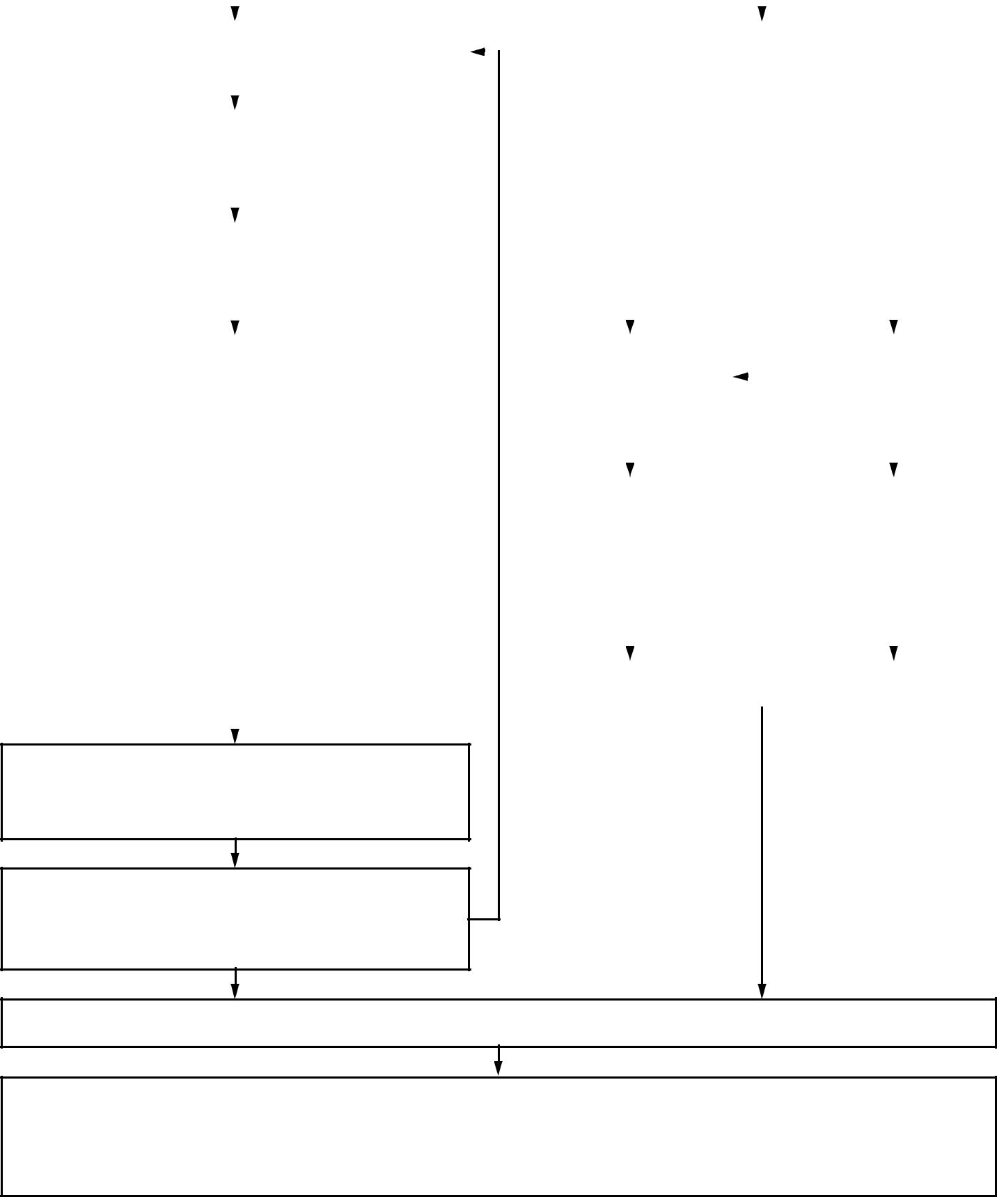
TROUBLESHOOTING CHART

Engine operation is not normal or the engine trouble warning light is on.
* Engine trouble warning light may not come on even if the engine operation is not normal.
| The engine trouble warning light comes on. | The engine trouble warning light does not come on. | ||||||||||||||
| Check the fault code number displayed on the meter. | Check the operation of following sensors and actua- | ||||||||||||||
| tors in the diagnostic mode. | |||||||||||||||
| Refer to “Diagnostic mode table”. | |||||||||||||||
| 01: Throttle position sensor (throttle angle) | |||||||||||||||
| Identify the system with the malfunction. | 30: Ignition coil | ||||||||||||||
| Refer to “FAIL-SAFE ACTION TABLE”. | 36: Fuel injector #1 | ||||||||||||||
| 37: Fuel injector #2 | |||||||||||||||
| Identify the probable cause of malfunction. | |||||||||||||||
| Refer to “Fault code table”. | |||||||||||||||
| OK | NG | ||||||||||||||
| Checking and repair the probable case of malfunction. | Malfunction of engine | Defective sensor or | |||||||||||||
| actuator | |||||||||||||||
| Fault code No. YES | Fault code No. NO | ||||||||||||||
| Check and repair. | Check and repair. | ||||||||||||||
| Check and repair the | Check and repair the | ||||||||||||||
| Refer to “TROUBLE- | Refer to “TROUBLE- | ||||||||||||||
| SHOOTING DETAILS”. | SHOOTING DETAILS”. | inner parts of engine. | corresponding sen- | ||||||||||||
| Monitor the operation of | Refer to chapter 5. | sor or actuator. | |||||||||||||
| the sensors and actua- | |||||||||||||||
| tors in the diagnostic | |||||||||||||||
| mode. | NG | ||||||||||||||
| Refer to “Diagnostic | |||||||||||||||
| mode table”. | |||||||||||||||
| Check the engine condition. | |||||||||||||||
|
|
|
|
|
|
Perform ECU (engine) reinstatement action.
Refer to “Reinstatement method” in “TROUBLE-
SHOOTING DETAILS”.
| Fault code number | |
| displayed | OK |
Turn the main switch to “OFF”, turn the main switch back to “ON”, and then check if the fault code number is still displayed.
Not fault code number displayed
Repairs completed
Erasing the malfunction history:*
The malfunction history is stored even if the main switch is turned OFF.
The malfunction history must be erased in the diagnostic mode.
Refer to “Diagnostic mode table (Diagnostic code No.62)”.
* Operated when the engine trouble warning light is on.
7 - 6

| FUEL INJECTION SYSTEM | FI | ||
| EAS00905 | ||||
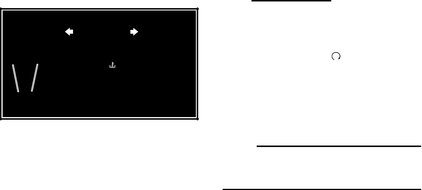
| DIAGNOSTIC MODE | ||||
| Setting the diagnostic mode | ||||
| 1. Turn the main switch to “OFF” and set the | ||||
| engine stop switch to “ ”. | ||||
| 2. Disconnect the wire harness coupler from | ||||
| the fuel pump. | ||||
| 3. Simultaneously press | and hold the | |||
| “SELECT” 1 and “RESET” 2 buttons, turn | ||||
| the main switch to “ON”, and continue to | ||||
| press the buttons for 8 seconds or more. | ||||
| NOTE: | ||||
| • All displays on the meter disappear except | ||||
| the clock and tripmeter displays. | ||||
| • “dIAG” appears on the tripmeter LCD. |

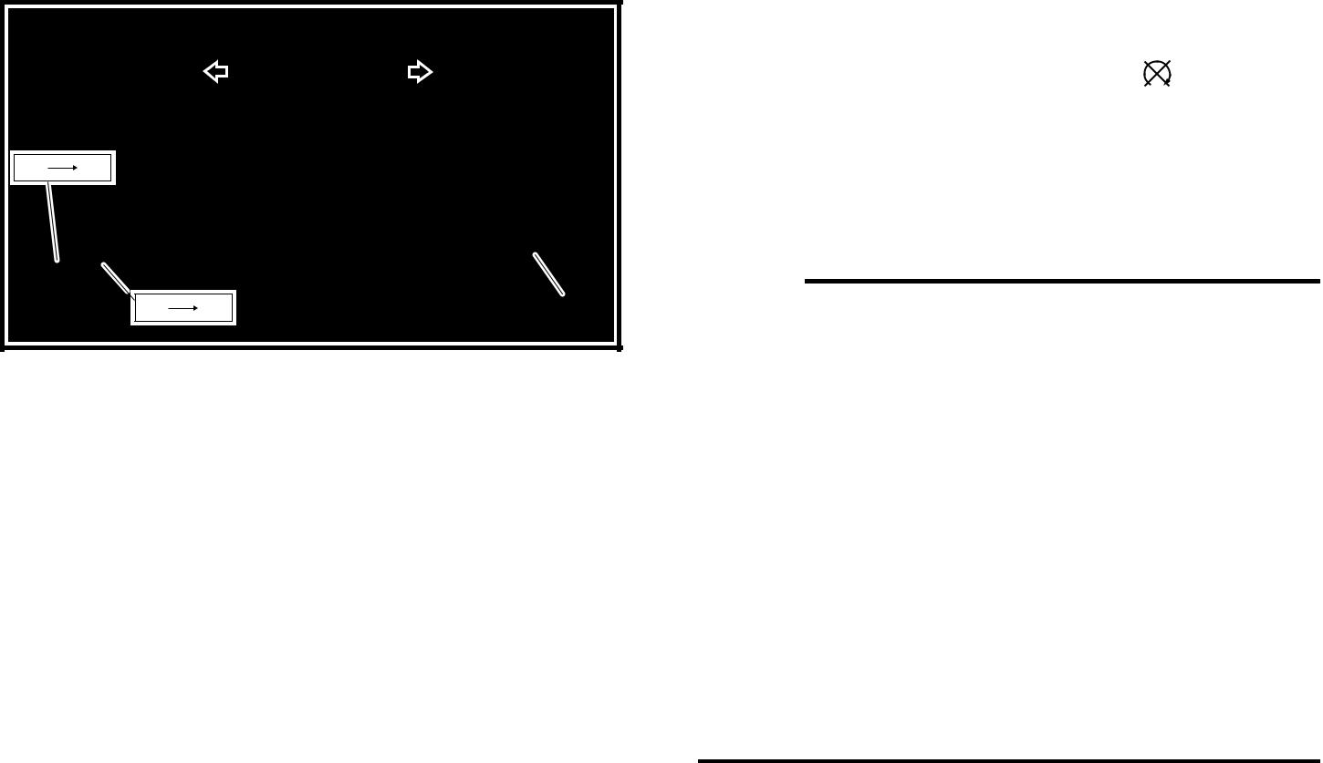
| 4. Press the “SELECT” button to select the CO | ||||||||
| adjustment mode “CO” or the diagnostic | ||||||||
| mode “dIAG”. | ||||||||
| 5. After selecting “dIAG”, simultaneously press | ||||||||
| the “SELECT” and “RESET” buttons for 2 | ||||||||
| seconds or more to execute the selection. | ||||||||
| 6. Set the engine stop switch to “ ”. | ||||||||
| 7. Select the diagnostic code number that | ||||||||
| applies to the item that was verified with the | ||||||||
| fault | code | number | by | pressing | the | |||
| “SELECT” and “RESET” buttons. | ||||||||
| NOTE: | ||||||||
| The diagnostic code number appears on the | ||||||||
| tripmeter LCD (01-70). | ||||||||
| • To decrease the selected diagnostic code | ||||||||
| number, press the “RESET” button. Press | ||||||||
| the “RESET” button for 1 second or longer to | ||||||||
| automatically decrease the diagnostic code | ||||||||
| numbers. | ||||||||
| • To increase the selected diagnostic code | ||||||||
| number, press the “SELECT” button. Press | ||||||||
| the “SELECT” button for 1 second or longer | ||||||||
| to automatically increase the diagnostic code | ||||||||
| numbers. |
7 - 7
| FUEL INJECTION SYSTEM | FI | |||
К Verify the operation of the sensor or actua-tor.
Sensor operation
The data representing the operating condi-tions of the sensor appears on the trip LCD.
Actuator operation
Set the engine stop switch to “  ” to oper-ate the actuator.
NOTE:

If the engine stop switch is set to “ ”, set it to “  ”, and then set it to “
  ” again.

Л Turn the main switch to “OFF” to cancel the diagnostic mode.
7 - 8
| FUEL INJECTION SYSTEM | FI | ||||||
| EAS00906 | |||||||
| Fault code table | |||||||
| Fault | Symptom | Probable cause of malfunction | Diagnostic code | ||||
| code No. | |||||||
| No normal signals are received from | • Open or short circuit in wiring harness. | ||||||
| the crankshaft position sensor. | • Defective crankshaft position sensor. | ||||||
| • Malfunction in pickup rotor. | — | ||||||
| • Malfunction in ECU (engine). | |||||||
| • Improperly installed sensor. | |||||||
| Intake air pressure sensor-open or | • Open or short circuit in wiring harness. | ||||||
| short circuit detected. | • Defective intake air pressure sensor. | ||||||
| • Malfunction in ECU (engine). | |||||||
| Faulty intake air pressure sensor | • Intake air pressure sensor hose is detached, clogged, | ||||||
| hose system; a hose is detached, | kinked, or pinched. | ||||||
| causing constant application of the | • Malfunction in ECU (engine). | ||||||
| atmospheric pressure to the sensor; | |||||||
| or, the hose is clogged. | |||||||
| Throttle position sensor-open or short | • Open or short circuit in wiring harness. | ||||||
| circuit detected. | • Defective throttle position sensor. | ||||||
| • Malfunction in ECU (engine). | |||||||
| • Improperly installed throttle position sensor. | |||||||
| A stuck throttle position sensor is | • Stuck throttle position sensor. | ||||||
| detected. | • Malfunction in ECU (engine). | ||||||
| Open circuit in the input line from the | • Open circuit in wiring harness. | ||||||
| sidestand switch to the ECU (engine) | • Malfunction in ECU (engine). | ||||||
| is detected when the start switch is | |||||||
| pressed. | |||||||
| Coolant temperature sensor-open or | • Open or short circuit in wiring harness. | ||||||
| short circuit detected. | • Defective coolant temperature sensor. | ||||||
| • Malfunction in ECU (engine). | |||||||
| • Improperly installed sensor. | |||||||
| Intake air temperature sensor-open or | • Open or short circuit in wiring harness. | ||||||
| short circuit detected. | • Defective intake air temperature sensor. | ||||||
| • Malfunction in ECU (engine). | |||||||
| • Improperly installed sensor. | |||||||
| No normal signals are received from | • Open or short circuit in wiring harness. | ||||||
| the O2 sensor. | • Defective O2 sensor. | — | |||||
| • Malfunction in ECU (engine). | |||||||
| • Improperly installed sensor. | |||||||
| The scooter has overturned. | • Overturned. | ||||||
| • Malfunction in ECU (engine). | |||||||
| Open circuit is detected in the primary | • Open circuit in wiring harness. | ||||||
| lead of the ignition coil. | • Malfunction in ignition coil. | ||||||
| • Malfunction in ECU (engine). | |||||||
| • Malfunction in a component of ignition cut-off circuit sys- | |||||||
| tem. | |||||||
| Faulty the FID valve. | • Stuck the FID valve (when fully open). | ||||||
| • Malfunction in ECU (engine). | |||||||
| Lean angle cut-off switch-open or | • Open or short circuit in wiring harness. | ||||||
| short circuit detected. | • Defective lean angle cut-off switch. | ||||||
| • Malfunction in ECU (engine). | |||||||
| Supply power to the fuel injector and | • Open circuit in wiring harness. (red/blue line) | ||||||
| fuel pump is not normal. | • Malfunction in ECU (engine). | ||||||
| • Defective fuel injection system relay. | |||||||
| An error is detected while reading or | • Malfunction in ECU (engine). (The CO adjustment value | ||||||
| writing on EEPROM. | is not properly written on or read from the internal mem- | ||||||
| ory.) | |||||||
7 - 9
| FUEL INJECTION SYSTEM | FI | ||||||
| Fault | Symptom | Probable cause of malfunction | Diagnostic code | ||||
| code No. | |||||||
| Power supply to the fuel injection sys- | • Open circuit in wiring harness. (blue/yellow – red/black | ||||||
| tem relay is not normal. | line) | — | |||||
| • Malfunction in “CHARGING SYSTEM” in chapter 8. | |||||||
| Faulty ECU (engine) memory. When | • Malfunction in ECU (engine). (The program and data are | ||||||
| this malfunction is detected, the code | not properly written on or read from the internal mem- | — | |||||
| number might not appear on the | ory.) | ||||||
| meter. | |||||||
|
|
|
