 |


Starting circuit cut-off system operation (xp500)
|
|
|
|
If the engine stop switch is set to “  ” and the main switch is set to “ON” (both switches are closed), the starter motor can only operate if the following conditions are met:


Ч A brake lever is pulled to the handlebar (the brake light switch is closed) and the side-
stand is up (the sidestand switch is closed).
Ш Battery
Ш Main fuse
Ш Main switch
Ш Ignition fuse
Ш Engine stop switch
Ш Starting circuit cut-off relay 1
Ш Sidestand switch
Ш Signaling system fuse
Ш Front brake light switch
0 Rear brake light switch A Start switch
B Starter relay C Starter motor
8 - 17
 ELECTRIC STARTING SYSTEM ELEC – +
| D | ||
| M | ||
| C | ||
| A | ||
| B |

EAS00756
STARTING CIRCUIT CUT-OFF SYSTEM OPERATION (XP500A)
If the engine stop switch is set to “  ” and the main switch is set to “ON” (both switches are closed), the starter motor can only operate if the following conditions are met:

GG A brake lever is pulled to the handlebar (the brake light switch is closed) and the side-
stand is up (the sidestand switch is closed).
Й Battery
Й Main fuse
Й Main switch
Й Signaling system fuse
Й Ignition fuse
Й Engine stop switch
Й Starting circuit cut-off relay 1
Й Front brake light switch
Й Rear brake light switch
0 Sidestand switch
К Starting circuit cut-off relay 2
К Start switch
К Starter relay
К Starter motor
8 - 18
| ELEC | |||||||||||
| ELECTRIC STARTING SYSTEM | –+ | ||||||||||
| EAS00757 | EAS00739 |
TROUBLESHOOTING
The starter motor fails to turn.
Check:
Л main, ignition and signaling system fuses
Л battery
Л starter motor
Л starting circuit cut-off relay 1
Л starting circuit cut-off relay 2 (XP500A)
Л starter relay
Л main switch
Л engine stop switch
Л sidestand switch
10.brake light switch (front and rear) 11.start switch
12.wiring connections
|
|
|
(of the entire starting system)
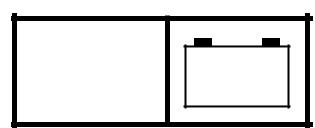
М Battery
Check the condition of the battery.
Refer to “CHECKING AND CHARGING THE BATTERY” in chapter 3.
Minimum open-circuit voltage 12.8 V or more at 20 °C (68 °F)
• Is the battery OK?
| YES | NO | |||

• Clean the battery terminals.
• Recharge or replace the battery.
EAS00758
NOTE:

Н Before troubleshooting, remove the following part(s):
О front cowling
О leg shield
О footrest board
О fuel tank
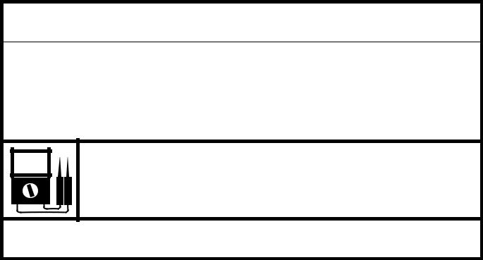
П Troubleshoot with the following special tool(s).


Pocket tester 90890-03112, YU-03112-C
EAS00738
Р Main, ignition and signaling system fuses
Check the main, ignition and signaling sys-tem fuses for continuity.
Refer to “CHECKING THE FUSES” in chapter 3.
Are the main, ignition and signaling sys-tem fuses OK?
| YES | NO | |||


Replace the fuse(s).
С Starter motor
Connect the positive battery terminal 1 and starter motor lead 2 with a jumper lead 3.


 WARNING

У A wire that is used as a jumper lead must have at least the same capacity or more as that of the battery lead, other-wise the jumper lead may burn.
У This check is likely to produce sparks, therefore make sure nothing flammable is in the vicinity.

• Does the starter motor turn?
| YES | NO | |||

Repair or replace the starter motor.
8 - 19
ELECTRIC STARTING SYSTEM ELEC – +
EAS00759
Ф Starting circuit cut-off relay 1
Remove the starting circuit cut-off relay 1.
Connect the pocket tester (Ω Ч 1) and bat-tery (12 V) to the starting circuit cut-off relay 1 terminals as shown.
Positive battery terminal → red/black 1 Negative battery terminal → light green 2
XP500
Positive tester probe → green/yellow 3 Negative tester probe → green/yellow 4
XP500A
Positive tester probe → blue/white 3 Negative tester probe → white/red 4
| XP500 | XP500A |

ХDoes the starting circuit cut-off relay 1 have continuity between green/yellow and green/yellow?
| YES | NO | |||

Replace the starting circuit cut-off relay 1.
Ш Starting circuit cut-off relay 2 (XP500A)
Remove the starting circuit cut-off relay 2.
Connect the pocket tester (Ω Ч 1) and bat-tery (12 V) to the starting circuit cut-off relay 2 terminals as shown.
Check the starting circuit cut-off relay 2 for continuity.
Positive battery terminal →
green/yellow 1 Negative battery terminal → black 2
|
|
|
Positive tester probe → white/red 3 Negative tester probe → green/white 4

ЩDoes the starting circuit cut-off relay 2 have continuity between white/red and green/white?
| YES | NO | |||

Replace the starting circuit cut-off relay 2.
8 - 20
| ELEC | |||||||||||
| ELECTRIC STARTING SYSTEM | –+ | ||||||||||
| EAS00761 | EAS00750 |
Ъ Starter relay
Remove the starter relay.
Connect the pocket tester (Ω Ч 1) and bat-tery (12 V) to the starter relay terminals as shown.
XP500
Positive battery terminal → black 1 Negative battery terminal →
blue/white 2
XP500A
Positive battery terminal → red/white 1 Negative battery terminal →
blue/white 2
Positive tester probe → red 3 Negative tester probe → black 4

Ы Does the starter relay have continuity between red and black?
| YES | NO | |||
Replace the starter relay.
EAS00749
7. Main switch
Ь Engine stop switch
Check the engine stop switch for continu-ity.
Refer to “CHECKING THE SWITCHES”.
Is the engine stop switch OK?
| YES | NO | |||
Replace the right handlebar switch.
EAS00752
Э Sidestand switch
Check the sidestand switch for continuity. Refer to “CHECKING THE SWITCHES”.
Is the sidestand switch OK?
| YES | NO | |||
Replace the side-stand switch.
EAS00751
10.Brake light switch (front and rear)
Ю Check the brake light switches for continu-ity.
Refer to “CHECKING THE SWITCHES”.
Ю Is each brake light switch OK?
| YES | NO | |||

Replace the brake light switch(es).
Я Check the main switch for continuity. Refer to “CHECKING THE SWITCHES”.
Я Is the main switch OK?
| YES | NO | |||

Replace the main switch/immobilizer unit.
8 - 21
ELECTRIC STARTING SYSTEM ELEC – +
EAS00764
11.Start switch
А Check the start switch for continuity. Refer to “CHECKING THE SWITCHES”.
А Is the start switch OK?
| YES | NO | |||
Replace the right handlebar switch.
EAS00766
12.Wiring
ХCheck the entire starting system’s wiring. Refer to “CIRCUIT DIAGRAM (XP500)” or “CIRCUIT DIAGRAM (XP500A)”.
ХIs the starting system’s wiring properly connected and without defects?


YES
The starting system circuit is OK.
NO
Properly connect or repair the starting system’s wiring.
|
|
|
8 - 22
STARTER MOTOR ELEC – +
EAS00767
STARTER MOTOR

| Order | Job/Part | Q’ty | Remarks |
| Removing the starter motor | Remove the parts in the order listed. | ||
| Fuel tank | Refer to “FUEL TANK” in chapter 3. | ||
| Negative battery lead | Disconnect. | ||
| Starter motor lead | Disconnect. | ||
| Starter motor | |||
| For installation, reverse the removal pro- | |||
| cedure. | |||
8 - 23
STARTER MOTOR ELEC – +

| Order | Job/Part | Q’ty | Remarks |
| Disassembling the starter motor | Remove the parts in the order listed. | ||
| Front bracket | |||
| O-ring | |||
| Shims | |||
| Lock washer | |||
| Oil seal | |||
| Bearing | |||
| Rear bracket | |||
| Shims | |||
| Brush holder set | |||
| Armature assembly | |||
| A | Starter motor yoke | ||
| For assembly reverse the disassembly | |||
| procedure. | |||
8 - 24
STARTER MOTOR ELEC – +
EAS00770
|
|
|
