 |


Description of the laboratory plant
|
|
|
|
By the matter of fact, the laboratory plant is done as a stand. Functional logical model of researched system is constructed in the left part of stand with a help of functional elements Ei,where i=1…12 with one, two or three inputs. The state of functional elements is set with the help of switches “1”-”0”. Affirmatively functional element is represented as a coincidence scheme, which is built on relay. There is a signal at the output of the functional element, only in that case, if the signals are transferred to the inputs and a switch is turned in the position “1”.There are also busses of external input impacts and stimulating signals x1, x2,x3 in the left part of a stand. In the central part of the stand there is a block of comparators, designed for permissible control of output signals of functional elements by the criterion “permissible”, “un-permissible”. Logical operations “OR”, which are necessary for analysis of state attribute are done on the commutating jacks of output busses of comparator blocks. Comparators are built on the electromagnetic relays. For indication of attributes lamps Л1-Л10 are used. The light is on, if the controllable signal yj is in the permissible range, that is corresponds to yj=1. If yj=0, the light is off.
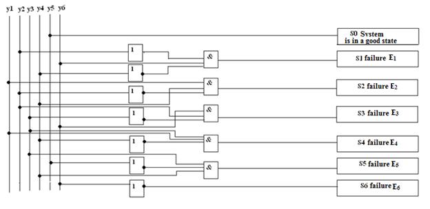
Fig. 3
Logical elements “AND” and “NOT”, on which the research scheme of faults is built and indication block built on lamps as a panel S0-S10 are situated in the right part of stand. The panel S0 is light,when the diagnosing object is in good state. The panel Si, i=1..10 is light on, when the failure of i-th element occurs.
Tasks:
1. To build the matrix of conditions for teacher given FLM. (tab. 1)
2. To make FLM on the stand and to research it.
3. To definite the common diagnostic test and to write down all переключательные functions for all conditions Si,  (tab. 3)
4. To define local miasmal diagnostic tests for all conditions Ti min and comparison to it Si (Ti min), tab. 11.
5. Построить и исследовать схему логического устройства (см. рис. 3), позволяющую определить работоспособность системы S0 и отказ любого из элементов модели Si,  .
.
The operation procedure:
1. For the researching of the FLM you have to:
-make the model on the stand,
-join all exits of functional elements with entrances of comparators,
-switch “on”,
- enter, with the help of switchers of the functional elements of model “1” – “0” refuses, to define on the display of block of comparators the meanings of the exit signals,
-check comparison of meanings of the exit results, what we have defined theoretically and been written down into the matrix of conditions.
2. For the defining of the common diagnostic test of the local minimal diagnostic tests and comporting switching functions to build:
|
|
|
- the minimal matrix of conditions
- the common diagnostic test and the comporting переключательные functions Si, (Td), I = 0,n (tab. 3)
- the matrixes for all Si, includes S0, and made it minimal, to define the local minimal diagnostic tests Ti min and comparison to it Si (Ti min) (tab. 11)
3. For the construction and researching the logical devise, what makes the algorithm of diagnostic you have to:
- based on the switching functions of conditions Si(Ti min) to build the scheme of final automat (fig.3), what have been realising the results of functions, what had been given
- make the scheme on the stand,
- turn on power,
- research the work of the logical devise, entering, with the help of the switchers “1” and “0” refusals into the functional elements of system.
All results write down at the tab. 12:
Table 12
| The number of the element, that refuses | The signal on the display of the block of indication | Remark |
| E1 | S1 | |
| E2 | S2 | |
| E3 | S3 | |
| E4 | S4 | |
| E5 | S5 | |
| E6 | S6 |
Control questions
1.Explain principles of construction of the functional-logical model.
2.Name the rules of construction of the matrix of condition?
3.Explain the rules of minimization of the matrix of condition
4.Name rules and consequence of minimization of the Boolean matrices.
5.Explain methodology of construction and work of logical device for determination of capacity and searching for of disrepairs.
|
|
|
