 |


Outline of anti-lock brake system (xp500a)
|
|
|
|
Yamaha ABS features
GEN

INFO
1. The Yamaha ABS (Anti-Lock Brake System) features a dual electronic control system, which acts on the front and rear brakes independently.
2. The ABS features a compact and lightweight design to help maintain the basic maneuverability of the vehicle.
3. The hydraulic unit, which is the main component of the ABS, is centrally located on the vehicle to
increase mass centralization.
EAS00872
The operation of the Yamaha ABS brakes is the same as conventional vehicle, with a right hand brake lever for operating the front wheel brake and a left hand brake lever for operating the rear wheel brake.
When wheel lockup is detected during emergency braking, hydraulic control is performed by the hydraulic system independently.
EAS00877
The ABS also includes a highly developed self-diagnostic function. The ABS detects any problem conditions and allows normal braking even if the ABS is not operating properly.
When this occurs, the ABS warning light on the meter assembly comes on.
The ABS stores the malfunction codes in the memory of the ECU (ABS) for easy problem identifica-tion and troubleshooting.
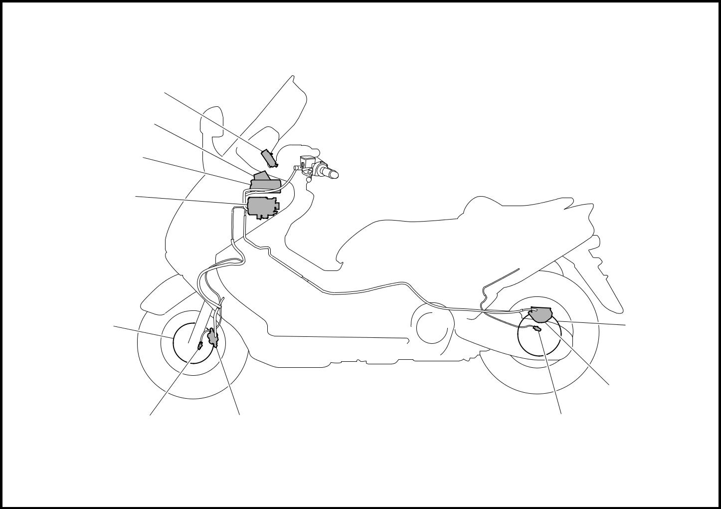
ABS layout
| 1 ABS warning light | 5 Rear disc rotor | 9 Front wheel sensor |
| 2 Fail-safe relay | 6 Rear brake caliper | 0 Front disc rotor |
| 3 Electronic control unit (ECU) | 7 Rear wheel sensor | |
| 4 Hydraulic unit | 8 Front brake caliper |
1 - 4
GEN
FEATURES INFO
ABS block diagram
| 1 Rear brake master cylinder | 6 Hydraulic control valve | A Rear wheel sensor |
| 2 Hydraulic unit | 7 Front brake master cylinder | B Front wheel sensor |
| 3 Hydraulic pump | 8 Rear brake caliper | C ABS warning light |
| 4 ABS motor | 9 Front brake caliper | |
| 5 Buffer chamber | 0 ECU (ABS) | |

1 - 5
GEN
FEATURES INFO
EAS00873
Useful terms
• Wheel speed:
The rotation speed of the front and rear wheels.
• Chassis speed:
The speed of the chassis.
When the brakes are applied, wheel speed and chassis speed are reduced. However, the chassis travels forward by its inertia even though the wheel speed is reduced.
• Brake force:
The force applied by braking to reduce the wheel speed.
• Wheel lock:
A condition that occurs when the rotation of one or both of the wheels has stopped but the vehicle continues to travel.
• Side force:
The force on the tires which supports the vehicle when cornering.
|
|
|
• Slip ratio:
When the brakes are applied, slipping occurs between the tires and the road sur-face. This causes a difference between the wheel speed and the chassis speed.
Slip ratio is the value that shows the rate of wheel slippage and is defined by the follow-ing formula.
| Chassis speed – Wheel speed | ||
| Slip ratio = | Ч 100 (%) | |
| Chassis speed |
0%:
There is no slip between the wheel and the road surface. The chassis speed is equal to the wheel speed.
100%:
The wheel speed is “0”, but the chassis is moving (i.e., wheel lock).
1 - 6
GEN
FEATURES INFO
| И | Brake force | ||
| force between the | |||
| road surface | Side force | ||
| Friction | tire and | ||
| Slip ratio (%) | |||
| Й | Less slippery | ||
| the | road surface | ||
| Friction force betweentireandroadsurface | Controlling zone | ||
| Slippery road surface | |||
| Slip ratio (%) | |||
| Vehicle speed | |||
| Wheel speed | |||
| Pressurized | |||
| Depressurized | |||
| Brake force | |||


EAS00874
|
|
|
