 |


Do not touch the handlebar grip until the rubber adhesive has fully dried.
|
|
|
|

▲▲▲▲▲▲▲▲▲▲▲ ▲▲▲▲▲▲▲▲▲ ▲▲▲▲▲▲▲▲▲▲▲▲
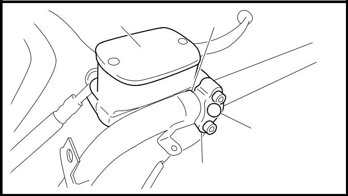
Ф Install:
rear brake master cylinder 1
rear brake master cylinder holder 2
| T.R. | 10 Nm (1.0 m · kg, 7.2 ft · lb) |

NOTE:

Х Install the rear brake master cylinder holder with the “UP” mark facing up a.
Х Align the rear brake master cylinder with the projection b in the handlebar.
Х First, tighten the upper bolt, then the lower bolt.
4 - 70

a
b
Ш b
UP
a
HANDLEBAR CHAS
Щ  Connect:
rear brake lock lever cable
NOTE:

Lubricate the inside of the rear brake lock lever cable and parking brake lever with a thin coat of lithium-soap-based grease.

Ъ Install:
left handlebar switch 1
NOTE:
Align the projection a on the right handlebar switch with the hole b in the handlebar.
Ы Install:
front brake master cylinder 1
front brake master cylinder holder 2
| T.R. | 10 Nm (1.0 m · kg, 7.2 ft · lb) |
NOTE:

ЬInstall the front brake master cylinder holder with the “UP” a mark facing up.
ЬAlign the front brake master cylinder with the projection b in the handlebar.
ЬFirst, tighten the upper bolt, then the lower bolt.

Э Install:
throttle grip
throttle cables
NOTE:
Lubricate the inside of the throttle grip with a thin coat of lithium-soap-based grease and install it onto the handlebar.
4 - 71
HANDLEBAR CHAS
Ю Install:
right handlebar switch 1

 WARNING

Make sure the throttle grip operates smoothly.
NOTE:
Align the projection a on the right handlebar switch with the hole b in the handlebar.
10.Adjust:
Я throttle cable free play
Refer to “ADJUSTING THE THROTTLE CABLE FREE PLAY” in chapter 3.

Throttle cable free play (at the flange of the throttle grip)
3 ~ 5 mm (0.12 ~ 0.20 in)
11.Adjust:
А rear brake lock lever cable length
Refer to “ADJUSTING THE REAR BRAKE LOCK LEVER CABLE” in chapter 3.
4 - 72
FRONT FORK CHAS
FRONT FORK

| Order | Job/Part | Q’ty | Remarks |
| Removing the front fork | Remove the parts in the order listed. | ||
| The following procedure applies to both | |||
| of the front fork legs. | |||
| Front cowling/leg shield | Refer to “COVER AND PANEL” in chap- | ||
| ter 3. | |||
| Handlebar cover (upper and lower) | Refer to “HANDLEBAR”. | ||
| Front wheel | Refer to “FRONT WHEEL AND BRAKE | ||
| DISC”. | |||
| ECU (ABS) | For XP500A | ||
| Refer to “FRONT AND REAR BRAKES”. | |||
| Front fender | |||
| Front brake caliper | |||
| Horn coupler | Disconnect. | ||
| Horn | |||
|
|
|
4 - 73
FRONT FORK CHAS
| Order | Job/Part | Q’ty | Remarks | |||
| Upper bracket pinch bolt | Loosen. | Refer to “REMOVING | ||||
| Cap bolt | Loosen. | THE FRONT FORK | ||||
| Lower bracket pinch bolt | Loosen. | LEGS” and “INSTALLING | ||||
| Front fork leg | THE FRONT FORK | |||||
| LEGS”. | ||||||
| For installation, reverse the removal pro- | ||||||
| cedure. | ||||||
4 - 74
FRONT FORK CHAS

| Order | Job/Part | Q’ty | Remarks | ||
| Disassembling the front fork leg | Remove the parts in the order listed. | ||||
| The following procedure applies to both | |||||
| of the front fork legs. | |||||
| Cap bolt | |||||
| O-ring | |||||
| Spacer | |||||
| Fork spring seat | |||||
| Fork spring | Refer to “DISASSEMBLING THE | ||||
| Damper rod assembly bolt | FRONT FORK LEGS” and “ASSEM- | ||||
| Copper washer | BLING THE FRONT FORK LEGS”. | ||||
| Damper rod assembly | |||||
| Rebound spring | |||||
| Oil flow stopper | |||||
| A | Inner tube | ||||
4 - 75
FRONT FORK CHAS
| Order | Job/Part | Q’ty | Remarks | ||
| B | Inner tube bushing | ||||
| C | Dust seal | Refer to “DISASSEMBLING THE | |||
| D | Oil seal clip | ||||
| FRONT FORK LEGS” and “ASSEM- | |||||
| E | Oil seal | ||||
| BLING THE FRONT FORK LEGS”. | |||||
| F | Washer | ||||
| G | Outer tube bushing | For assembly, reverse the disassembly | |||
| procedure. | |||||
|
|
|
4 - 76
FRONT FORK CHAS
EAS00651
REMOVING THE FRONT FORK LEGS
The following procedure applies to both of the front fork legs.
1. Stand the scooter on a level surface.
 WARNING
Securely support the scooter so that there is no danger of it falling over.
NOTE:
Place the scooter on a suitable stand so that the front wheel is elevated.

Х Loosen:
upper bracket pinch bolt 1
cap bolt 2
Х Loosen:
lower bracket pinch bolts 1

 WARNING
Before loosening the upper and lower
Bracket pinch bolts, support the front fork
Leg.
Ц Remove:
front fork leg
EAS00652
|
|
|
