 |


Inner-rotor-to-outer-rotor-tip clearance
|
|
|
|
0.04 ~ 0.12 mm
(0.0016 ~ 0.0047 in) <Limit>: 0.20 mm (0.0079 in)
Outer-rotor-to-oil-pump-housing clearance
0.045 ~ 0.085 mm
(0.0018 ~ 0.0033 in) <Limit>: 0.15 mm (0.0059 in)
Oil-pump-housing-to-inner-and-outer-rotor clearance
0.11 ~ 0.23 mm
(0.0043 ~ 0.0091 in) <Limit>: 0.30 mm (0.0118 in)
Л Check:
oil pump operation
Unsmooth → Repair or replace the defec-tive part(s).

5 - 45
 OIL PUMP ENG
EAS00365
CHECKING THE RELIEF VALVE

М Check:
relief valve body 1
relief valve 2
spring 3
O-ring 4
Damage/wear → Replace the defective part(s).
EAS00367
CHECKING THE OIL DELIVERY PIPES
The following procedure applies to all of the oil delivery pipes.
Н  Check:
oil delivery pipe 1 Damage → Replace.
Obstruction → Wash and blow out with compressed air.
EAS00368
CHECKING THE OIL STRAINER
О Check:
oil strainer
Damage → Replace.
Contaminants → Clean with engine oil.
CHECKING THE OIL PUMP DRIVE CHAIN
П Check:
oil pump drive chain
Cracks/stiffness → Replace the oil pump chain, oil pump drive and driven sprocket as a set.

ASSEMBLING THE OIL PUMP
Р Lubricate:
inner rotor
outer rotor
oil pump driven gear
(with the recommended lubricant)

Recommended lubricant
Engine oil
5 - 46
|
| OIL PUMP ENG |
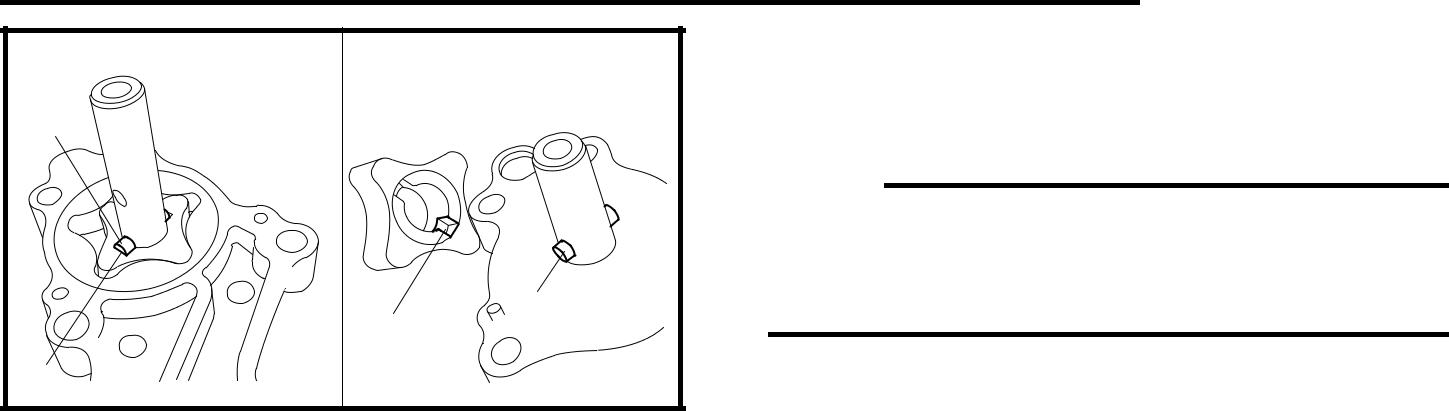
| 2. Install: | |
| • pins | |
| • inner rotors | |
| NOTE: | |
| When installing the inner rotor, align the pin 1 | |
| in the oil pump shaft with the groove a on the | |
| inner rotor. | |
| a | |
| a | 3. Check: |
| • oil pump operation | |
| Refer to “CHECKING THE OIL PUMP”. |

5 - 47
 CLUTCH ENG


CLUTCH


| Order | Job/Part | Q’ty | Remarks | ||
| Removing the clutch | Remove the parts in the order listed. | ||||
| A.C. magneto cover | Refer to “STARTER CLUTCH AND A.C. | ||||
| MAGNETO ROTOR”. | |||||
| Clutch assembly nut | Refer to “REMOVING THE CLUTCH” | ||||
| Clutch assembly | and “INSTALLING THE CLUTCH”. | ||||
| For installation, reverse the removal pro- | |||||
| cedure. | |||||
|
|
|
5 - 48
CLUTCH ENG

| Order | Job/Part | Q’ty | Remarks | ||
| Disassembling the clutch | Remove the parts in the order listed. | ||||
| Circlip | |||||
| Spring stopper plate | |||||
| Clutch damper spring 2 | |||||
| Pressure plate | |||||
| Clutch plate 2 | Refer to “DISASSEMBLING THE | ||||
| Clutch damper spring 1 | CLUTCH” and “ASSEMBLING THE | ||||
| Friction plate | CLUTCH”. | ||||
| Clutch plate 1 | |||||
| Clutch spring | |||||
| Thrust plate | |||||
| A | Clutch boss nut | ||||
| B | Primary drive gear | ||||
| C | Bearing | ||||
5 - 49
CLUTCH ENG
| Order | Job/Part | Q’ty | Remarks |
| D | Circlip | ||
| E | Bearing | ||
| F | Clutch boss | ||
| G | Collar | ||
| H | Weight | ||
| I | Clutch housing | ||
| For assembly, reverse the disassembly | |||
| procedure. | |||
5 - 50
CLUTCH ENG
REMOVING THE CLUTCH

С Remove:
clutch assembly nut 1
clutch assembly 2
NOTE:

У Before removal, apply a and b alignment marks.
У While holding the clutch assembly with the rotor holding tool 3, loosen the clutch assembly nut.
У Align these marks during reassembly.

Rotor holding tool 90890-01235, YU-01235
DISASSEMBLING THE CLUTCH

Ф Remove:
circlip 1
NOTE:
Install the clutch spring compressor 2 onto the clutch assembly as shown. Then, com-press the spring, and remove the circlip.


Clutch spring compressor 90890-01482

Х Remove:
spring stopper plate 1
clutch damper spring 2
pressure plate
clutch plate 2
friction plate
clutch plate 1
clutch damper spring 1
thrust plate
clutch springs
NOTE:
One to three holes a are drilled in the spring stopper plate to adjust the balance of the clutch assembly. Before removing the spring stopper plate, make alignment marks on both the plate and the clutch housing so that the plate can be reinstalled in its original position.
5 - 51
CLUTCH ENG

Ш Remove:
clutch boss nut 1
NOTE:
While holding the clutch boss 2 with the clutch holding tool 3, loosen the clutch boss nut.
|
|
|

Clutch holding tool 90890-04086, YM-91042
EAS00280
 CHECKING THE FRICTION PLATES
The following procedure applies to all of the friction plates.
Щ Check:
friction plate
Damage/wear → Replace the friction plates as a set.
Щ Measure:
friction plate thickness
Out of specification → Replace the friction plates as a set.
NOTE:
Measure the friction plate at four places.


Friction plate thickness
2.75 ~ 3.05 mm (0.108 ~ 0.120 in) <Limit>: 2.65 mm (0.104 in)
EAS00281
|
|
|
