 |
Securely support the vehicle so that there is no danger of it falling over.
|
|
|
|

Ц Place the vehicle on the centerstand.
Ц Set the main switch to “OFF”.
Ц Remove:
front cowling
battery
Refer to “FUEL TANK” in chapter 3.
Ц Check:
battery voltage

Battery voltage
Higher than 12.8 V
Lower than 12.8 V → Charge or replace the battery.

NOTE:

Ч If the battery voltage is lower than 12.8 V, charge the battery and perform hydraulic unit operation test 2.
Ч If the battery voltage is lower than 10 V, the ABS warning light comes on and the ABS does not operate.

Ш Connect the test coupler adaptor 1 to the test coupler 2.

Test coupler adaptor 90890-03149
4 - 124
 ANTI-LOCK BRAKE SYSTEM (XP500A) CHAS
| Main switch | ON | |||||
| OFF | ||||||
| On | Flashing | |||||
| ABS | ||||||
| warning | 2.0 | 3.0 | 0.5 | 0.5 | 0.5 | |
| light | ||||||
| sec- | sec- | sec- | sec- | sec- | ||
| onds | onds | ond | ond | ond |

ABS motor

1 2
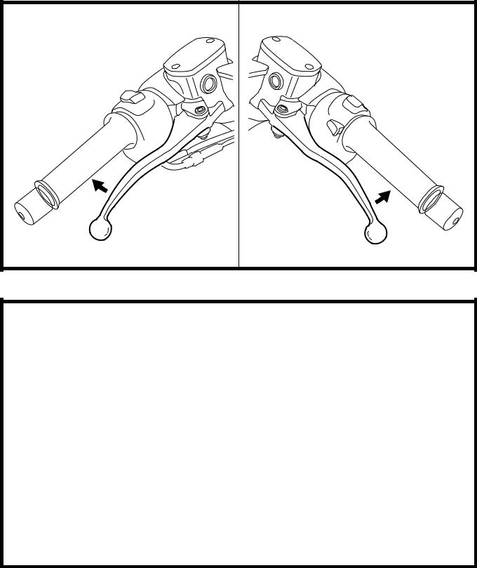
Ъ Set the main switch to “ON” while operating the brake levers simultaneously.
CAUTION:

When the main switch is set to “ON”, be sure to operate both the brake levers simul-taneously. If only the brake levers are oper-ated, set the main switch to “OFF” and start the procedure again.

Ы Check:
Hydraulic unit operation
When the main switch is set to “ON”, the ABS warning light comes on for 2 seconds, goes off for 3 seconds, then starts flashing. When the ABS warning light starts flashing, the front brake lever 1 will return to its home position. The rear brake lever 2 will then return to its home position, then the front brake lever will return to its home posi-tion again.
CAUTION:

Ь Check that the front brake lever returns to its home position before the rear brake lever returns to its home position.
Ь If the rear brake lever returns to its home position before the front brake lever does, check that the brake hoses are connected correctly to the hydraulic unit.
Ь If either the brake levers returns to its home position slowly, check that the brake hoses are connected correctly to the hydraulic unit.
If the operation of the hydraulic unit is nor-mal, delete all of the malfunction codes.


• [D-6-4] Deleting the malfunction codes
Э Connect the test coupler adaptor 1 to the test coupler 2. (Refer to “[B-5] ABS mal-function check using the ABS self-diagnosis (present malfunction)”.)
Э Set the main switch to “ON”.
The multifunction display indicates previ-ously recorded malfunction codes.
|
|
|
4 - 125
 ANTI-LOCK BRAKE SYSTEM (XP500A) CHAS

| Main switch | ON | ||||||
| OFF | |||||||
| On | Flashing | ||||||
| ABS | |||||||
| warning | 2.0 | 3.0 | 0.5 | 0.5 | 0.5 | 0.5 | |
| light | sec- | sec- | sec- | sec- | sec- | sec- | |
| onds | onds | ond | ond | ond | ond | ||
| ABS motor | |||||||

3. Set the engine stop switch 1 to “  ”.
”.
CAUTION:

Be sure to set the engine stop switch to “  ”. If the start switch is pushed without setting the engine stop switch to “
  ”, the starter motor gears or other parts may be damaged.

Ю Push the start switch 2 at least 10 times in 4 seconds to delete the malfunction codes.
Ю The multifunction meter display switches to the ODO/TRIP display and the ABS warn-ing light flashes in 0.5 second intervals when the malfunction codes are deleted.
А Set the main switch to “OFF”.
А Set the main switch to “ON”.
Check that the ABS warning light comes on for 2 seconds, goes off for 3 seconds, then starts flashing to confirm that all malfunction codes are deleted.
А Set the main switch to “OFF”.
А Disconnect the test coupler adaptor from the test coupler and install the protective cap onto the test coupler.
NOTE:

Do not forget to install the protective cap onto the test coupler.

CAUTION:

Since the malfunction codes remain in the memory of the ECU (ABS) until they are deleted, always delete the malfunction codes after the service has been com-pleted.

• [D-6-5] Trial run
After all checks and service have been com-pleted, make sure that the motorcycle has no problems by performing a trial run at a speed faster than 10 km/h.
4 - 126
 ANTI-LOCK BRAKE SYSTEM (XP500A) CHAS
• [D-6-6] Delete function test
1. Place the vehicle on the centerstand. 2. Set the main switch to “OFF”.
3. Connect the test coupler adapter to the test coupler.
4. Set the main switch to “ON”. 5. Check:
• ECU (ABS) voltage
Connect the pocket tester (DC 20 V) to the ECU (ABS) coupler.
Positive tester probe → brown/white 1 Negative tester probe → black/white 2

Battery voltage
Higher than 12.8 V
Lower than 12.8 V → Charge or replace the battery.
6. Check:
• ECU (ABS)-to-start-switch-lead continuity Connect the pocket tester (Ω Ч 1) to the ECU (ABS) coupler and start switch cou-pler.

Positive tester probe →
green/white 1 (ECU) Negative tester probe →
green/white 2 (start switch)
No continuity → Replace or repair the wire harness.
7. Check:

• ECU (ABS) voltage
Connect the pocket tester (DC 20 V) to the ECU (ABS) coupler.
|
|
|
Positive tester probe → green/white 1 Negative tester probe → black/white 2
Push the start switch.

|
|
|


