 |


The camshaft cap bolts must be tightened evenly or damage to the cylinder head, camshaft cap, and camshafts will result.
|
|
|
|

NOTE:

Lubricate the camshaft cap bolt threads with engine oil.
5 - 14
 CAMSHAFTS ENG
Ь Install:
timing chain tensioner gasket
timing chain tensioner

▼▼▼▼▼▼▼▼▼▼▼ ▼▼▼▼▼▼▼▼▼ ▼▼▼▼▼▼▼▼▼▼▼▼
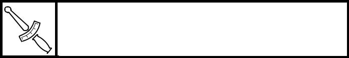
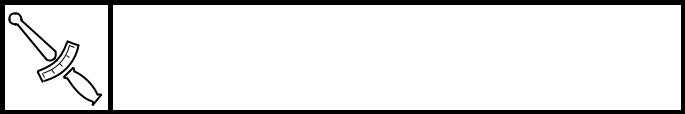
Э Lightly press the timing chain tensioner rod into the timing chain tensioner housing by hand.
Э While pressing the timing chain tensioner rod, wind it clockwise with a thin screwdriver 1 until if stops.
Э With the screwdriver still inserted into the timing chain tensioner, install the timing chain tensioner 2, gasket onto the cylinder block. Then, tighten the timing chain ten-sioner bolts 3 to the specified torque.

 WARNING

Always use a new gasket.

T.
R.
Timing chain tensioner bolt 10 Nm (1.0 m · kg, 7.2 ft · lb)
А Remove the screwdriver, make sure that the timing chain tensioner rod releases, and tighten the timing chain tensioner cap bolt to the specified torque.
T.
R.
Timing chain tensioner cap bolt 7 Nm (0.7 m · kg, 5.1 ft · lb)
▲▲▲▲▲▲▲▲▲▲▲ ▲▲▲▲▲▲▲▲▲ ▲▲▲▲▲▲▲▲▲▲▲▲
Б Turn:
crankshaft (several turns counterclockwise)
Б Check:
“I” mark a
Make sure that the “I” mark is aligned with the stationary pointer b.
camshaft sprocket alignment marks c Make sure that the camshaft sprocket align-ment mark is aligned with the cylinder head
edge d.
Out of alignment → Reinstall.
Refer to the installation steps above.


5 - 15
CAMSHAFTS ENG
Л Measure:
valve clearance
Out of specification → Adjust.
Refer to “ADJUSTING THE VALVE CLEARANCE” in chapter 3.
Л Install:
• cylinder head cover gasket New
• cylinder head cover

T.
R.
10 Nm (1.0 m · kg, 7.2 ft · lb)
NOTE:
Tighten the cylinder head cover bolts in stages and in a crisscross pattern.
5 - 16
CYLINDER HEAD ENG
CYLINDER HEAD

| Order | Job/Part | Q’ty | Remarks |
| Removing the cylinder head | Remove the parts in the order listed. | ||
| Intake and exhaust camshafts | Refer to “CAMSHAFTS”. | ||
| Cylinder head | Refer to “REMOVING THE CYLINDER | ||
| HEAD” and “INSTALLING THE CYLIN- | |||
| DER HEAD”. | |||
| Cylinder head gasket | |||
| Dowel pin | |||
| For installation, reverse the removal pro- | |||
| cedure. | |||
|
|
|
5 - 17
CYLINDER HEAD ENG
REMOVING THE CYLINDER HEAD
М Remove:
cylinder head bolts
cylinder head nuts

NOTE:
Н Loosen the nuts and bolts in the proper sequence as shown.
Н Loosen each nut 1/2 of a turn at a time. After all of the nuts are fully loosened, remove them.

EAS00229
CHECKING THE CYLINDER HEAD
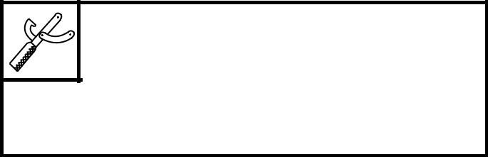
О Eliminate:
combustion chamber carbon deposits (with a rounded scraper)
NOTE:
Do not use a sharp instrument to avoid damag-ing or scratching:
П spark plug bore threads
П valve seats
Р Check:
cylinder head Damage/scratches → Replace.
cylinder head water jacket Mineral deposits/rust → Eliminate.
Р Measure:
cylinder head warpage
Out of specification → Resurface the cylin-der head.

Maximum cylinder head warpage 0.03 mm (0.0012 in)
▼▼▼▼▼▼▼▼▼▼▼ ▼▼▼▼▼▼▼▼▼ ▼▼▼▼▼▼▼▼▼▼▼▼
С Place a straightedge 1 and a thickness gauge 2 across the cylinder head.
С Measure the warpage.
С If the limited is exceeded, resurface the cyl-inder head as follows.
С Place a 400 ~ 600 grit wet sandpaper on the surface plate and resurface the cylinder head using a figure-eight sanding pattern.

NOTE:
To ensure an even surface, rotate the cylinder head several times.
▲▲▲▲▲▲▲▲▲▲▲ ▲▲▲▲▲▲▲▲▲ ▲▲▲▲▲▲▲▲▲▲▲▲
5 - 18
CYLINDER HEAD ENG
INSTALLING THE CYLINDER HEAD
Т Install:
dowel pins
cylinder head gasket New
Т Install:
cylinder head
NOTE:
Pass the timing chain through the timing chain cavity.
У Tighten:
cylinder head nuts 1


T.
R.
35 Nm (3.5 m · kg, 25 ft · lb)
• cylinder head nuts 2
T.
R.
46 Nm (4.6 m · kg, 33 ft · lb)
• cylinder head bolts 3

T.
R.
10 Nm (1.0 m · kg, 7.2 ft · lb)
NOTE:
Ф Apply engine oil onto the threads of the cylin-der head nuts.
Ф Tighten the cylinder head nuts and bolts in the proper tightening sequence as shown and torque them in two stages.

5 - 19
VALVES AND VALVE SPRINGS ENG
VALVES AND VALVE SPRINGS

| Order | Job/Part | Q’ty | Remarks | ||
| Removing the valves and valve | Remove the parts in the order listed. | ||||
| springs | |||||
| Cylinder head | Refer to “CYLINDER HEAD”. | ||||
| Valve lifter | |||||
| Valve pad | |||||
| Valve cotter | |||||
| Valve retainer | |||||
| Valve spring | Refer to “REMOVING THE VALVES” | ||||
| Valve stem seal | and “INSTALLING THE VALVES”. | ||||
| Valve spring seat | |||||
| Valve guide | |||||
| Intake valve | |||||
| Exhaust valve | For installation, reverse the removal pro- | ||||
| cedure. | |||||
|
|
|
5 - 20
VALVES AND VALVE SPRINGS ENG
EAS00237
REMOVING THE VALVES
The following procedure applies to all of the valves and related components.
NOTE:
Before removing the internal parts of the cylin-der head (e.g., valves, valve springs, valve seats), make sure that the valves properly seal.
13 Remove:
valve lifter 1
valve pad 2

NOTE:
Make a note of the position of each valve lifter and valve pad so that they can be reinstalled in their original place.
И Check:
valve sealing
Leakage at the valve seat → Check the valve face, valve seat, and valve seat width. Refer to “CHECKING THE VALVE SEATS”.

▼▼▼▼▼▼▼▼▼▼▼ ▼▼▼▼▼▼▼▼▼ ▼▼▼▼▼▼▼▼▼▼▼▼
Й Pour a clean solvent a into the intake and exhaust ports.
Й Check that the valves properly seal.
NOTE:
There should be no leakage at the valve seat
1.
▲▲▲▲▲▲▲▲▲▲▲ ▲▲▲▲▲▲▲▲▲ ▲▲▲▲▲▲▲▲▲▲▲▲
К Remove:
valve cotters 1
NOTE:
Remove the valve cotters by compressing the valve spring with the valve spring compressor 2 and valve spring compressor attachment

3.
|
|
|
