 |


Checking the clutch plates
|
|
|
|
The following procedure applies to all of the clutch plates.
Ъ Check:
clutch plate
Damage → Replace the clutch plates as a set.
Ъ Measure:
clutch plate warpage
(with a surface plate and thickness gauge
1)
Out of specification → Replace the clutch plates as a set.

Maximum clutch plate warpage Clutch plate 1
Mm (0.0039 in) Clutch plate 2
Mm (0.0079 in)
5 - 52
 CLUTCH ENG


CHECKING THE CLUTCH SPRINGS AND
CLUTCH DAMPER SPRINGS
The following procedure applies to all of the clutch springs.
Ы Check:
clutch spring
Damage → Replace the clutch springs as a set.
Ы Measure:
clutch spring free length a
Out of specification → Replace the clutch spring.

Clutch spring limit 25.4 mm (1.00 in)
Ь Measure:
clutch damper spring 1 b
Out of specification → Replace the clutch damper spring 1.

Clutch damper spring 1 limit
Mm (0.11 in)
Ю Measure:
clutch damper spring 2 c
Out of specification → Replace the clutch damper spring 2.

Clutch damper spring 2 limit 4.40 mm (0.17 in)
EAS00284
CHECKING THE CLUTCH HOUSING

Я Check:
clutch housing dogs
Damage/pitting/wear → Deburr the clutch housing dogs or replace the clutch housing.
NOTE:

Pitting on the clutch housing dogs will cause erratic clutch operation.

5 - 53
CLUTCH ENG
EAS00285
CHECKING THE CLUTCH BOSS

А Check:
clutch boss splines
Damage/pitting/wear → Replace the clutch boss.
NOTE:
Pitting on the clutch boss splines will cause erratic clutch operation.
EAS00286
CHECKING THE PRESSURE PLATE AND

THRUST PLATE
Х Check:
pressure plate
thrust plate
Cracks/damage → Replace.
CHECKING THE WEIGHT

Ц Check:
weight
Cracks/wear/scaling/chipping → Replace. Out of specification → Replace.

Weight outside diameter 16.0 mm (0.63 in) <Limit>: 15.5 mm (0.61 in)
ASSEMBLING THE CLUTCH
Ч Lubricate:
friction plates
clutch plates
(with the recommended lubricant)

Recommended lubricant
Engine oil
5 - 54
CLUTCH ENG

Ш Install:
clutch boss
primary drive gear
clutch boss nut 1
Ш Tighten:
clutch boss nut
| T.R. | 90 Nm (9.0 m · kg, 65 ft · lb) |

NOTE:
While holding the clutch boss 2 with the clutch holding tool 3, tighten the clutch boss nut.
|
|
|

Clutch holding tool 90890-04086, YM-91042
Ъ Install:
clutch damper spring 1 1
clutch plate 2 2
friction plate 3
clutch plate 1 4

И Engine side
5 - 55
CLUTCH ENG
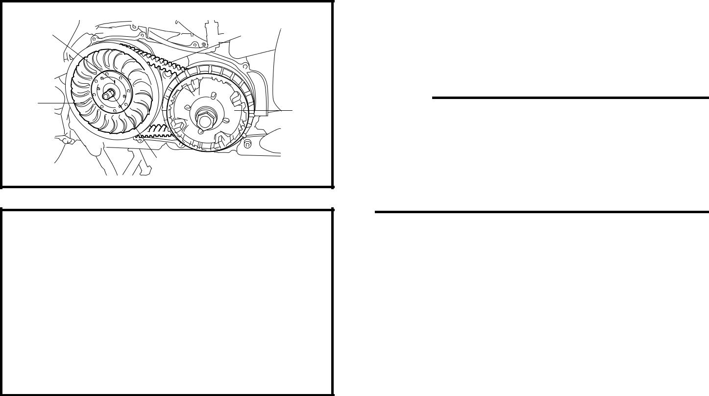
INSTALLING THE CLUTCH

Ы Install:
clutch assembly 1
clutch assembly nut 2

T.
R.
65 Nm (6.5 m · kg, 47 ft · lb)
NOTE:
ЬAlign the a and b during reassembly.
ЬWhile holding the clutch assembly with the rotor holding tool 3, tighten the clutch assembly nut.

Rotor holding tool 90890-01235, YU-01235
5 - 56
 V-BELT AUTOMATIC TRANSMISSION ENG
V-BELT AUTOMATIC TRANSMISSION

V-BELT CASE

| Order | Job/Part | Q’ty | Remarks |
| Removing the V-belt case | Remove the parts in the order listed. | ||
| Muffler | Refer to “ENGINE REMOVAL”. | ||
| V-belt case cover 1 | |||
| V-belt case cover 2 | |||
| V-belt case air filter cover | |||
| V-belt case air filter element | |||
| Lead holder | |||
| V-belt case | |||
| V-belt case gasket | |||
| Bearing retainer | |||
| Bearing | |||
| Circlip | |||
| Oil seal | |||
| Bearing | |||
| For installation, reverse the removal pro- | |||
| cedure. | |||
5 - 57
V-BELT AUTOMATIC TRANSMISSION ENG
V-BELT AND PRIMARY/SECONDARY SHEAVE
*1 Shell BT grease 3®
 *2 BEL-RAY assembly lube®
| Order | Job/Part | Q’ty | Remarks | ||
| Removing the V-belt and primary/ | Remove the parts in the order listed. | ||||
| secondary sheave | |||||
| V-belt case air filter element (left) | Refer to “WATER PUMP” in chapter 6. | ||||
| Primary sheave nut | |||||
| Spacer | |||||
| O-ring | Refer to “REMOVING THE PRIMARY | ||||
| Primary sheave assembly | SHEAVE ASSEMBLY, SECONDARY | ||||
| Primary fixed sheave | SHEAVE ASSEMBLY AND V-BELT” | ||||
| Secondary sheave nut | and “INSTALLING THE PRIMARY | ||||
| Secondary sheave assembly | SHEAVE ASSEMBLY, SECONDARY | ||||
| Collar | SHEAVE ASSEMBLY AND V-BELT”. | ||||
| O-ring | |||||
| V-belt | |||||
| Right crankcase cover | |||||
|
|
|
5 - 58
V-BELT AUTOMATIC TRANSMISSION ENG
*1 Shell BT grease 3®
*2 BEL-RAY assembly lube®
| Order | Job/Part | Q’ty | Remarks | |||
| V-belt case air duct joint clamp | Loosen. | Refer to “INSTALLING | ||||
| V-belt case air duct | THE PRIMARY SHEAVE | |||||
| ASSEMBLY, SECOND- | ||||||
| ARY SHEAVE ASSEM- | ||||||
| BLY AND V-BELT”. | ||||||
| Plate | ||||||
| V-belt case air duct seal | ||||||
| For installation, reverse the removal pro- | ||||||
| cedure. | ||||||
5 - 59
V-BELT AUTOMATIC TRANSMISSION ENG
* BEL-RAY assembly lube®

| Order | Job/Part | Q’ty | Remarks | ||
| Disassembling the primary sheave | Remove the parts in the order listed. | ||||
| Cam | Refer to “DISASSEMBLING THE PRI- | ||||
| Slider | MARY SHEAVE” and “ASSEMBLING | ||||
| Weight | THE PRIMARY SHEAVE”. | ||||
| Primary sliding sheave | |||||
| Collar | |||||
| For assembly, reverse the disassembly | |||||
| procedure. | |||||
5 - 60
V-BELT AUTOMATIC TRANSMISSION ENG
* BEL-RAY assembly lube®

| Order | Job/Part | Q’ty | Remarks | ||
| Disassembly the secondary sheave | Remove the parts in the order listed. | ||||
| Secondary sheave spring seat nut | Refer to “DISASSEMBLING THE SEC- | ||||
| ONDARY SHEAVE” and “ASSEMBLING | |||||
| THE SECONDARY SHEAVE”. | |||||
| Upper spring seat | |||||
| Compression spring | |||||
| Spring seat | |||||
| Secondary sliding sheave | Refer to “ASSEMBLING THE SECOND- | ||||
| Oil seal | ARY SHEAVE”. | ||||
| O-ring | |||||
| Guide pin | |||||
| Secondary fixed sheave | For assembly, reverse the disassembly | ||||
| procedure. | |||||
5 - 61
V-BELT AUTOMATIC TRANSMISSION ENG
| REMOVING THE PRIMARY SHEAVE | ||||
| ASSEMBLY, SECONDARY SHEAVE | ||||
| ASSEMBLY AND V-BELT | ||||
| 1. Remove: | ||||
| • primary sheave nut 1 | ||||
| • secondary sheave nut 2 | ||||
| NOTE: | ||||
| While | holding the primary | and secondary | ||
| sheave with the sheave holder, loosen the nut. | ||||
| Sheave holder | ||||
| 90890-01481 | ||||

|
|
|
| 2. Install: | |
| • bolts 1 | |
| NOTE: | |
| Insert M6 bolts (more than 45 mm (1.77 in)) | |
| into the holes of the secondary sheave assem- | |
| bly, and then tighten the bolts to open the sec- | |
| ondary sheave assembly. |

| 3. Remove: | |||
| a | • secondary sheave assembly 1 | ||
| • primary sheave assembly 2 | |||
| • V-belt 3 | |||
| NOTE: | |||
| • Before removal, apply a and b alignment | |||
| marks. | |||
| b | • Align these marks during reassembly. | ||
| • Remove the primary sliding sheave, second- | |||
| ary sheave assembly and V-belt together. | |||
| 4. Remove: | |||
| • primary fixed sheave 1 |
5 - 62
V-BELT AUTOMATIC TRANSMISSION ENG
|
|
|
