 |
Installing the crankshaft main
|
|
|
|

JOURNAL BEARINGS
У Attach:
crankshaft main journal bearings
NOTE:

Attach the crankshaft main journal bearing to the plane bearing installer 1.


Plane bearing installer 90890-04139
Ф Install:
crankshaft main journal bearings 2
NOTE:

14 Align the projection a on the bearing with the projection b on the crankcase.
15 Place an iron 3 plate beneath the crankcase and press fit until the end of the plain bearing installer touches the iron plate.

INSTALLING THE CONNECTING RODS
И Install:
big end bearings 1

NOTE:

Й Align the projection a of the big end bear-ings with the notches b in the connecting rod cap.
Й Install each big end bearing in its original place.

К Install:
connecting rods

NOTE:

Л The stamped “Y” mark a on the connecting rods should face towards the left side of the crankcase.
Л Install each connecting rod in its original place.

5 - 80
 CRANKCASE AND CRANKSHAFT ENG
М Install:
connecting rod cap

NOTE:

Be sure that the characters a on the side of the cap and connecting rod are aligned.

П Tighten:
nuts (connecting rod cap)

T.
R.
16 Nm (1.6 m · kg, 11 ft · lb) + 90°
NOTE:

Apply molybdenum disulfide grease to the rod cap bolt threads and nut surfaces.

▼▼▼▼▼▼▼▼▼▼▼ ▼▼▼▼▼▼▼▼▼ ▼▼▼▼▼▼▼▼▼▼▼▼
Р Replace the connecting rod bolts and nuts with new ones.
CAUTION:

Tighten the connecting rod bolts using the plastic-region tightening angle method. Always install new bolts and nuts.

С Clean the connecting rod bolts and nuts.
С Tighten the connecting rod nuts with speci-fied torque.
С Put a mark 1 on the corner of the connect-ing rod nut 2 and the connecting rod 3.
С Tighten the nut further to reach the speci-fied angle (90°).

 WARNING

When the nut is tightened more than the specified angle, do not loosen the nut and then retighten it.

Replace the bolt with a new one and per-form the procedure again.

CAUTION:

Т Do not use a torque wrench to tighten the nut to the specified angle.
Т Tighten the nut until it is at the specified angles.

NOTE:

When using a hexagonal nut, note that the angle from one corner to another is 60°.

▲▲▲▲▲▲▲▲▲▲▲ ▲▲▲▲▲▲▲▲▲ ▲▲▲▲▲▲▲▲▲▲▲▲
5 - 81
|
|
|
 CRANKCASE AND CRANKSHAFT ENG
У Install:
balancer connecting rod
connecting rod cap

T.
R.
60 Nm (6.0 m · kg, 43 ft · lb)
CAUTION:

Х When tightening the nuts be sure to use an F-type torque wrench.
Х Without pausing, tighten to full torque specification. Apply continuous torque 57 ~ 63 Nm (5.7 ~ 6.3 m · kg, 41 ~ 45 ft · lb). Once you reach 57 Nm (5.7 m · kg, 41 ft · lb) DO NOT STOP TIGHTENING until final torque is reached. If the tightening is inter-rupted 57 ~ 63 Nm (5.7 ~ 6.3 m · kg, 41 ~ 45 ft · lb) loosen the nut to less than 57 Nm (5.7 m · kg, 41 ft · lb) and start again.

INSTALLING THE CRANKSHAFT

П Install:
crankshaft assembly 1
balancer piston cylinder 2

T.
R.
58 Nm (5.8 m · kg, 42 ft · lb)
CAUTION:

To avoid scratching the crankshaft and to ease the installation procedure, apply grease onto the oil seal lips and apply engine oil onto each bearing.

EAS00418
ASSEMBLING THE CRANKCASE
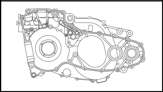
Р Thoroughly clean all the gasket mating sur-faces and crankcase mating surfaces.
5 - 82
 CRANKCASE AND CRANKSHAFT ENG
2. Apply:

• sealant
(onto the crankcase mating surfaces)

Yamaha bond No. 1215 90890-85505
Sealant (Quick Gasket®) ACC-11001-05-01
NOTE:

Do not allow any sealant to come into contact with the oil gallery.

3. Install:
• dowel pins
• left crankcase
5 - 83
 TRANSMISSION ENG
TRANSMISSION

| Order | Job/Part | Q’ty | Remarks |
| Removing the transmission | Remove the parts in the order listed. | ||
| Left crankcase | Refer to “CRANKCASE AND CRANK- | ||
| SHAFT”. | |||
| Secondary shaft | |||
| Main axle | |||
| Primary driven gear | |||
| First pinion gear | |||
| Washer | |||
| Drive axle | |||
| First wheel gear | |||
| Circlip | |||
| Bearing | |||
| Oil seal | |||
| For installation, reverse the removal pro- | |||
| cedure. | |||
5 - 84
 TRANSMISSION ENG
REMOVING THE TRANSMISSION
С Remove:
left crankcase
Refer to “CRANKCASE AND CRANK-SHAFT”.
С Remove:
secondary shaft 1
main axle 2
drive axle 3
primary driven gear 4
first wheel gear 5
first pinion gear

EAS00425
CHECKING THE TRANSMISSION

У Measure:
main axle runout
(with a centering device and dial gauge) Out of specification → Replace the main axle.

Maximum main axle runout
Mm (0.0031 in)
Ц Measure:
drive axle runout
(with a centering device and dial gauge) Out of specification → Replace the drive axle.

|
|
|
Maximum drive axle runout
Mm (0.0031 in)
● Measure:
• secondary shaft runout
(with a centering device and dial gauge) Out of specification → Replace the second-ary shaft.

|
|
|


