 |


Adjusting the valve clearance
|
|
|
|
The following procedure applies to all of the valves.
NOTE:

• Valve clearance adjustment should be made on a cold engine, at room temperature.
• When the valve clearance is to be measured or adjusted, the piston must be at top dead center (TDC) on the compression stroke.

1. Remove:
• front cowling
Refer to “FRONT COWLING”.
• footrest boards
• leg shield
• inner fender
Refer to “SIDE COVER MOULDINGS AND
LEG SHIELD”.
2. Remove:
• radiator
Refer to “RADIATOR AND OIL COOLER” in chapter 6.
3. Remove:
• spark plug
• cylinder head cover 1
• cylinder head cover gasket
4. Remove:
• throttle body
• intake manifold
Refer to “THROTTLE BODY” in chapter 7.
5. Remove:
• timing plug 1
6. Remove:
• V-belt case cover 1 1

3 - 11
 CHK
CHK
ADJUSTING THE VALVE CLEARANCE ADJ
b
a


7. Measure:
• valve clearance
Out of specification → Adjust.

Valve clearance (cold) Intake valve
0.15 ~ 0.20 mm
(0.0059 ~ 0.0079 in) Exhaust valve
0.25 ~ 0.30 mm
(0.0098 ~ 0.0118 in)
▼▼▼▼▼▼▼▼▼▼▼ ▼▼▼▼▼▼▼▼▼ ▼▼▼▼▼▼▼▼▼▼▼▼
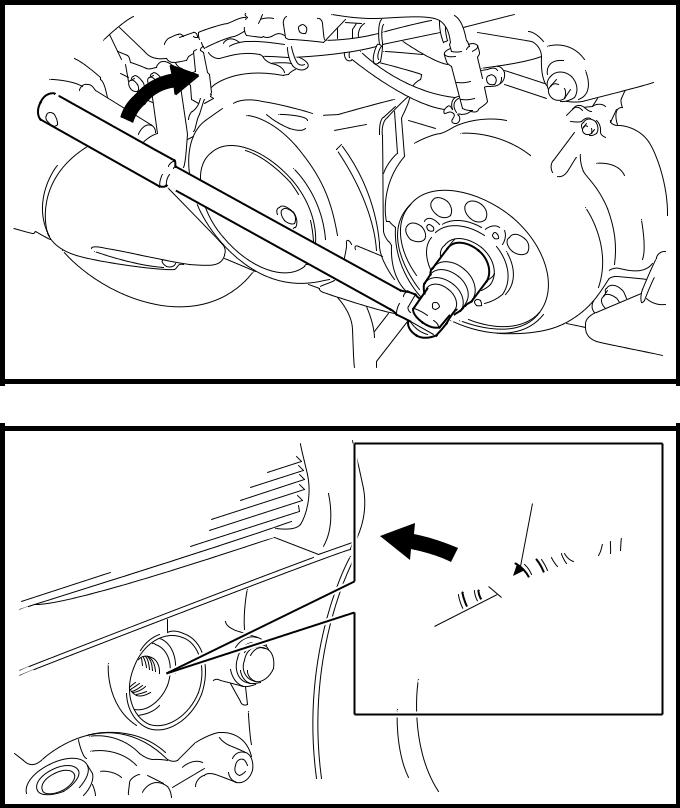
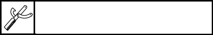
a. Turn the crankshaft counterclockwise.
b. When piston #1 is at TDC on the compres-sion stroke, align the “I” mark a on the A.C. magneto rotor with the stationary pointer b on the A.C. magneto cover.
NOTE:
• TDC on the compression stroke can be found when the camshaft lobes are turned away from each other.
• In order to be sure that the piston is at TDC, the alignment mark c on the intake cam-shaft sprocket and the alignment mark d on the exhaust camshaft sprocket must align with the cylinder head mating surface as shown in the illustration.
c. Measure the valve clearance with a thick-ness gauge 1.
Thickness gauge 90890-03079, YM-34483
NOTE:
• If the valve clearance is incorrect, record the measured reading.
• Measure the valve clearance in the following sequence.
d. Turn the crankshaft 360° counterclockwise and check the valve clearance of piston #2.
▲▲▲▲▲▲▲▲▲▲▲ ▲▲▲▲▲▲▲▲▲ ▲▲▲▲▲▲▲▲▲▲▲▲
3 - 12
ADJUSTING THE VALVE CLEARANCE
|
|
|
8. Remove:
• intake camshaft
• exhaust camshaft
CAUTION:
CHK
ADJ

Before removing the camshafts from the cylinder head, tilt up the engine at least 25°.
NOTE:
• Refer to “CAMSHAFTS” in chapter 5.
• When removing the timing chain and cam-shafts, fasten a wire to the timing chain to retrieve it if it falls into the crankcase.
9. Adjust:
• valve clearance
▼▼▼▼▼▼▼▼▼▼▼ ▼▼▼▼▼▼▼▼▼ ▼▼▼▼▼▼▼▼▼▼▼▼
a. Remove the valve lifter 1 and the valve pad
2.

Valve lapper 90890-04101

NOTE:
• Cover the timing chain opening with a rag to prevent the valve pad from falling into the crankcase.
• Make a note of the position of each valve lifter 1 and valve pad 2 so that they can be installed in the correct place.

b. Select the proper valve pad from the follow-ing table.

| Valve pad thick- | Available valve | |||
| ness range | pads | |||
| 1.20 ~ | 25 thicknesses in | |||
| Nos. | 2.40 mm | |||
| 0.05 mm (0.002 in) | ||||
| 120 ~ 240 | (0.0472 | ~ | ||
| increments | ||||
| 0.0945 in) | ||||
NOTE:

• The thickness a of each valve pad is marked in hundredths of millimeters on the side that touches the valve lifter.
• Since valve pads of various sizes are origi-nally installed, the valve pad number must be rounded in order to reach the closest equiva-lent to the original.
3 - 13
CHK
ADJUSTING THE VALVE CLEARANCE ADJ
c. Round off the original valve pad number according to the following table.
| Last digit | Rounded value |
| 0 or 2 | |
EXAMPLE:
Original valve pad number = 148 (thickness = 1.48 mm (0.058 in))
Rounded value = 150
d. Locate the rounded number of the original valve pad and the measured valve clear-ance in the valve pad selection table. The point where the column and row intersect is the new valve pad number.
NOTE:
The new valve pad number is only an approxi-mation. The valve clearance must be mea-2 sured again and the above steps should be
 repeated if the measurement is still incorrect.
| e. Install the new valve pad 1 and the valve | |
| lifter 2. |
NOTE:
Apply molybdenum disulfide to the valve pad.
• Lubricate the valve lifter with molybdenum disulfide oil.
• The valve lifter must turn smoothly when rotated by hand.
• Install the valve lifter and the valve pad in the correct place.
3 - 14
CHK
ADJUSTING THE VALVE CLEARANCE ADJ
12 Install the exhaust and intake camshafts, timing chain and camshaft caps.

T.
R.
Camshaft cap bolt
10 Nm (1.0 m · kg, 7.2 ft · lb)
|
|
|
NOTE:
13 Refer to “CAMSHAFTS” in chapter 5.
14 Lubricate the camshaft bearings, camshaft lobes and camshaft journals.
15 First, install the exhaust camshaft.
16 Align the camshaft sprocket marks with the edge of the cylinder head.
17 Turn the crankshaft counterclockwise sev-eral turns to seat the parts.
L Measure the valve clearance again.
M If the valve clearance is still out of specifica-tion, repeat all of the valve clearance adjust-ment steps until the specified clearance is
obtained.
▲▲▲▲▲▲▲▲▲▲▲ ▲▲▲▲▲▲▲▲▲ ▲▲▲▲▲▲▲▲▲▲▲▲
3 - 15
| ADJUSTING THE VALVE CLEARANCE | CHK | ||||||||||||||||||||||||||||
| ADJ | |||||||||||||||||||||||||||||
| VALVE PAD SELECTION TABLE | |||||||||||||||||||||||||||||
| INTAKE | |||||||||||||||||||||||||||||
| MEASURED VALVE | ORIGINAL VALVE PAD NUMBER | ||||||||||||||||||||||||||||
| CLEARANCE | |||||||||||||||||||||||||||||
| 0.00 ~ 0.02 | |||||||||||||||||||||||||||||
| 0.03 ~ 0.07 | |||||||||||||||||||||||||||||
| 0.08 ~ 0.10 | |||||||||||||||||||||||||||||
| 0.11 ~ 0.20 | STANDARD CLEARANCE | ||||||||||||||||||||||||||||
| 0.21 ~ 0.22 | |||||||||||||||||||||||||||||
| 0.23 ~ 0.27 | |||||||||||||||||||||||||||||
| 0.28 ~ 0.32 | |||||||||||||||||||||||||||||
| 0.33 ~ 0.37 | |||||||||||||||||||||||||||||
| 0.38 ~ 0.42 | |||||||||||||||||||||||||||||
| 0.43 ~ 0.47 | |||||||||||||||||||||||||||||
| 0.48 ~ 0.52 | |||||||||||||||||||||||||||||
| 0.53 ~ 0.57 | |||||||||||||||||||||||||||||
| 0.58 ~ 0.62 | |||||||||||||||||||||||||||||
| 0.63 ~ 0.67 | |||||||||||||||||||||||||||||
| 0.68 ~ 0.72 | |||||||||||||||||||||||||||||
| 0.73 ~ 0.77 | |||||||||||||||||||||||||||||
| 0.78 ~ 0.82 | Example: | ||||||||||||||||||||||||||||
| 0.83 ~ 0.87 | Valve clearance (cold) | ||||||||||||||||||||||||||||
| 0.88 ~ 0.92 | 0.11 ~ 0.20 mm (0.0043 ~ 0.0079 in) | ||||||||||||||||||||||||||||
| 0.93 ~ 0.97 | Rounded value 150 | ||||||||||||||||||||||||||||
| 0.98 ~ 1.02 | Measured valve clearance is 0.24 mm | ||||||||||||||||||||||||||||
| 1.03 ~ 1.07 | |||||||||||||||||||||||||||||
| (0.0094 in) | |||||||||||||||||||||||||||||
| 1.08 ~ 1.12 | |||||||||||||||||||||||||||||
| Replace pad 150 with pad 160 | |||||||||||||||||||||||||||||
| 1.13 ~ 1.17 | |||||||||||||||||||||||||||||
| Pad No. 150 = 1.50 mm (0.0591 in) | |||||||||||||||||||||||||||||
| 1.18 ~ 1.22 | |||||||||||||||||||||||||||||
| Pad No. 160 = 1.60 mm (0.0630 in) | |||||||||||||||||||||||||||||
| 1.23 ~ 1.27 | |||||||||||||||||||||||||||||
| Always install the valve pad with the number facing | |||||||||||||||||||||||||||||
| 1.28 ~ 1.32 | |||||||||||||||||||||||||||||
| 1.33 ~ 1.37 | down. | ||||||||||||||||||||||||||||
| EXHAUST | |||||||||||||||||||||||||||||
| MEASURED VALVE | ORIGINAL VALVE PAD NUMBER | ||||||||||||||||||||||||||||
| CLEARANCE | |||||||||||||||||||||||||||||
| 0.00 ~ 0.02 | |||||||||||||||||||||||||||||
| 0.03 ~ 0.07 | |||||||||||||||||||||||||||||
| 0.08 ~ 0.12 | |||||||||||||||||||||||||||||
| 0.13 ~ 0.17 | |||||||||||||||||||||||||||||
| 0.18 ~ 0.20 | |||||||||||||||||||||||||||||
| 0.21 ~ 0.30 | STANDARD CLEARANCE | ||||||||||||||||||||||||||||
| 0.31 ~ 0.32 | |||||||||||||||||||||||||||||
| 0.33 ~ 0.37 | |||||||||||||||||||||||||||||
| 0.38 ~ 0.42 | |||||||||||||||||||||||||||||
| 0.43 ~ 0.47 | |||||||||||||||||||||||||||||
| 0.48 ~ 0.52 | |||||||||||||||||||||||||||||
| 0.53 ~ 0.57 | |||||||||||||||||||||||||||||
| 0.58 ~ 0.62 | |||||||||||||||||||||||||||||
| 0.63 ~ 0.67 | |||||||||||||||||||||||||||||
| 0.68 ~ 0.72 | |||||||||||||||||||||||||||||
| 0.73 ~ 0.77 | |||||||||||||||||||||||||||||
| 0.78 ~ 0.82 | |||||||||||||||||||||||||||||
| 0.83 ~ 0.87 | Example: | ||||||||||||||||||||||||||||
| 0.88 ~ 0.92 | |||||||||||||||||||||||||||||
| 0.93 ~ 0.97 | Valve clearance (cold) | ||||||||||||||||||||||||||||
| 0.98 ~ 1.02 | 0.21 ~ 0.30 mm (0.0083 ~ 0.0118 in) | ||||||||||||||||||||||||||||
| 1.03 ~ 1.07 | Rounded value 175 | ||||||||||||||||||||||||||||
| 1.08 ~ 1.12 | Measured valve clearance is 0.35 mm | ||||||||||||||||||||||||||||
| 1.13 ~ 1.17 | |||||||||||||||||||||||||||||
| (0.0138 in) | |||||||||||||||||||||||||||||
| 1.18 ~ 1.22 | Replace pad 150 with pad 185 | ||||||||||||||||||||||||||||
| 1.23 ~ 1.27 | |||||||||||||||||||||||||||||
| Pad No. 175 = 1.75 mm (0.0689 in) | |||||||||||||||||||||||||||||
| 1.28 ~ 1.32 | |||||||||||||||||||||||||||||
| Pad No. 185 = 1.85 mm (0.0728 in) | |||||||||||||||||||||||||||||
| 1.33 ~ 1.37 | |||||||||||||||||||||||||||||
| Always install the valve pad with the number facing | |||||||||||||||||||||||||||||
| 1.38 ~ 1.42 | |||||||||||||||||||||||||||||
| down. | |||||||||||||||||||||||||||||
| 1.43 ~ 1.47 |

|
|
|
|
|
|
|
|
|
3 - 16
ADJUSTING THE VALVE CLEARANCE/
|
|
|
