 |


Radiator cap tester adapter 90890-01352, YU-33984
|
|
|
|
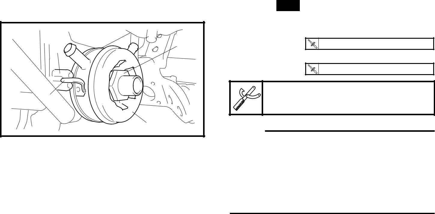
• Apply the specified pressure for ten sec-onds and make sure that there is no drop in
pressure.
▲▲▲▲▲▲▲▲▲▲▲ ▲▲▲▲▲▲▲▲▲ ▲▲▲▲▲▲▲▲▲▲▲▲
13. Check:
radiator fan Damage → Replace.
Malfunction → Check and repair.
Refer to “COOLING SYSTEM” in chapter 8.
6 - 3

| RADIATOR AND OIL COOLER | COOL | ||
| EAS00458 | ||||
| CHECKING THE OIL COOLER | ||||
| 1. Check: | ||||
| • oil cooler | ||||
| Cracks/damage → Replace. | ||||
| 2. Check: | ||||
| • oil cooler inlet hose | ||||
| • oil cooler outlet hose | ||||
| Cracks/damage/wear → Replace. | ||||
| EAS00459 | ||||
| INSTALLING THE OIL COOLER AND | ||||
| RADIATOR | ||||
| 1. Clean: | ||||
| • mating surfaces of the oil cooler and the | ||||
| crankcase | ||||
| (with a cloth dampened with lacquer thin- | ||||
| ner) | ||||
| 2. Install: | ||||
| • O-ring New | ||||
| • oil cooler 1 | ||||
| • oil cooler bolt 2 | ||||
| b | T.R. | 63 Nm (6.3 m · kg, 45 ft · lb) | ||
| • oil filter cartridge | ||||
| T.R. | 17 Nm (1.7 m · kg, 12 ft · lb) | |||
| a | Oil filter wrench | |||
| 90890-01469 | ||||
| NOTE: | ||||
| • Before installing the oil cooler, lubricate the | ||||
| oil cooler bolt with engine oil. | ||||
| • Make sure that the O-ring is positioned prop- | ||||
| erly. | ||||
| • Align the projection a on the oil cooler with | ||||
| the slot b in the crankcase. |
3. Fill:
• cooling system
(with the specified amount of the recom-mended coolant)
Refer to “CHANGING THE COOLANT” in chapter 3.
• crankcase
(with the specified amount of the recom-mended engine oil)
Refer to “CHANGING THE ENGINE OIL” in chapter 3.
6 - 4
 RADIATOR AND OIL COOLER COOL


| 4. Check: | ||
| • cooling system | ||
| Leaks → Repair or replace any faulty part. | ||
| ▼▼▼▼▼▼▼▼▼▼▼ ▼▼▼▼▼▼▼▼▼ ▼▼▼▼▼▼▼▼▼▼▼▼ | ||
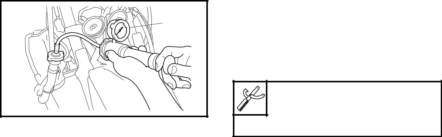
| a. Attach the radiator cap tester 1 to the radi- | ||
| ator. | ||
| Radiator cap tester | ||
| 90890-01325, YU-24460-01 | ||
| Radiator cap tester adapter | ||
| 90890-01352, YU-33984 | ||
| b. Apply 100 kPa (1.0 kg/cm2, 14.22 psi) of | ||
| pressure. | ||
| c. Measure the indicated pressure with the | ||
| gauge. | ||
| ▲▲▲▲▲▲▲▲▲▲▲ ▲▲▲▲▲▲▲▲▲ ▲▲▲▲▲▲▲▲▲▲▲▲ |
|
|
|
5. Measure:
• radiator cap opening pressure
Below the specified pressure → Replace the radiator cap.
Refer to “CHECKING THE RADIATOR”.
6 - 5
THERMOSTAT COOL
THERMOSTAT

| R. | 18 Nm (1.8 m | • | kg, 13 ft | • | Ib) |
| T. |
T.
R.
10 Nm (1.0 m • kg, 7.2 ft • Ib)
New 4
| Order | Job/Part | Q’ty | Remarks |
| Removing the thermostat | Remove the parts in the order listed. | ||
| Center cover/side cover | Refer to “COVER AND PANEL” in chap- | ||
| ter 3. | |||
| Coolant | Drain. | ||
| Refer to “CHANGING THE COOLANT” in | |||
| chapter 3. | |||
| Thermostat outlet hose | Disconnect. | ||
| Coolant temperature sensor coupler | Disconnect. | ||
| Coolant temperature sensor | |||
| Copper washer | |||
| Thermostat cover | |||
| Thermostat | Refer to “INSTALLING THE THERMO- | ||
| STAT”. | |||
| For installation, reverse the removal pro- | |||
| cedure. | |||
6 - 6


a
THERMOSTAT COOL

EAS00462
CHECKING THE THERMOSTAT
13. Check:
thermostat
Does not open at 69 ~ 73 °C (156.2 ~ 163.4 °F) → Replace.
▼▼▼▼▼▼▼▼▼▼▼ ▼▼▼▼▼▼▼▼▼ ▼▼▼▼▼▼▼▼▼▼▼▼
14. Suspend the thermostat in a container filled with water.
15. Slowly heat the water.
16. Place a thermometer in the water.
17. While stirring the water, observe the ther-mostat and thermometer’s indicated tem-
perature.
▲▲▲▲▲▲▲▲▲▲▲ ▲▲▲▲▲▲▲▲▲ ▲▲▲▲▲▲▲▲▲▲▲▲
|
|
|
16. Thermostat
17. Thermometer
18. Water
19. Container И Fully closed Й Fully opens
NOTE:

If the accuracy of the thermostat is in doubt, replace it. A faulty thermostat could cause seri-ous overheating or overcooling.

13. Check:
thermostat cover
thermostat housing (cylinder head) Cracks/damage → Replace.
EAS00467
INSTALLING THE THERMOSTAT
16. Install:
thermostat
thermostat cover
| T.R. | 10 Nm (1.0 m · kg, 7.2 ft · lb) |

NOTE:
Install the thermostat with its breather hole a facing forward.
2. Install:
• copper washer New
• coolant temperature sensor
| T.R. | 18 Nm (1.8 m · kg, 13 ft · lb) |

6 - 7
THERMOSTAT COOL
11. Fill:
• cooling system
(with the specified amount of the recom-mended coolant)
Refer to “CHANGING THE COOLANT” in chapter 3.
12. Check:
• cooling system
Leaks → Repair or replace any faulty part.
13. Measure:
• radiator cap opening pressure
Below the specified pressure → Replace the radiator cap.
Refer to “CHECKING THE RADIATOR”.
6 - 8
WATER PUMP COOL
WATER PUMP

| Order | Job/Part | Q’ty | Remarks |
| Removing the water pump | Remove the parts in the order listed. | ||
| Left upper side cover moulding/left | Refer to “COVER AND PANEL” in chap- | ||
| footrest board | ter 3. | ||
| Coolant | Drain. | ||
| Refer to “CHANGING THE COOLANT” in | |||
| chapter 3. | |||
| V-belt case air filter element clamp joint | Loosen. | ||
| V-belt case air filter element (left) | |||
| Generator cover protector cover | |||
| Generator cover protector | |||
| Oil cooler inlet hose | Disconnect. | ||
| Coolant hose | Disconnect. | ||
| Radiator outlet hose | Disconnect. | ||
| Water pump inlet pipe | |||
| Water pump outlet pipe | |||
6 - 9
WATER PUMP COOL
| Order | Job/Part | Q’ty | Remarks |
| Water pump assembly | Refer to “INSTALLING THE WATER | ||
| PUMP”. | |||
| For installation, reverse the removal pro- | |||
| cedure. | |||
6 - 10
WATER PUMP COOL

| Order | Job/Part | Q’ty | Remarks | ||||
| Disassembling the water pump | Remove the parts in the order listed. | ||||||
| NOTE: | |||||||
| It is not necessary to remove the impeller | |||||||
| shaft, unless the coolant level is extremely | |||||||
| low or coolant contains engine oil. | |||||||
| Water pump housing cover | |||||||
| O-ring | |||||||
| Circlip | |||||||
| Impeller shaft | Refer to “DISASSEMBLING THE | ||||||
| Water pump seal | |||||||
| WATER PUMP” and “ASSEMBLING | |||||||
| Bearing | |||||||
| THE WATER PUMP”. | |||||||
| Oil seal | |||||||
| Water pump housing | |||||||
| For assembly, reverse the disassembly | |||||||
| procedure. | |||||||
|
|
|
6 - 11
WATER PUMP COOL
EAS00471
|
|
|
