 |


Any of the following fail to light: turn signal light, brake light or an indicator light.
|
|
|
|
The horn fails to sound.
Check:
И main, signaling system, lighting system and backup fuses
И battery
И main switch
И wiring connections
(of the entire signaling system)
NOTE:

Й Before troubleshooting, remove the following part(s):
К battery cover
К rear cover
К front cowling
К handlebar cover
Л Troubleshoot with the following special tool(s).


Pocket tester 90890-03112, YU-03112-C
EAS00738
М Main, signaling system, lighting system and backup fuses
Check the main, signaling system, lighting system and backup fuses for continuity. Refer to “CHECKING THE FUSES” in chapter 3.
Are the main, signaling system, lighting system and backup fuses OK?


П Battery
Check the condition of the battery.
Refer to “CHECKING AND CHARGING THE BATTERY” in chapter 3.
Minimum open-circuit voltage 12.8 V or more at 20 °C (68 °F)
• Is the battery OK?
| YES | NO | |||

• Clean the battery terminals.
• Recharge or replace the battery.
EAS00749
Р Main switch
Check the main switch for continuity. Refer to “CHECKING THE SWITCHES”.
Is the main switch OK?
| YES | NO | |||
Replace the main switch/immobilizer unit.
EAS00795
С Wiring
Check the entire signal system’s wiring. Refer to “CIRCUIT DIAGRAM”.
Is the signaling system’s wiring properly connected and without defects?

| YES | NO | YES | NO |
| Replace the fuse(s). | Check the condition | Properly connect or | ||
| of each of the signal- | repair the signaling | |||
| ing system’s circuits. | system’s wiring. | |||
| Refer to “CHECK- | ||||
| ING THE SIGNAL- | ||||
| ING SYSTEM”. | ||||
8 - 41
 SIGNALING SYSTEM ELEC – +
EAS00796
CHECKING THE SIGNALING SYSTEM
Т The horn fails to sound.
Horn switch
Check the horn switch for continuity. Refer to “CHECKING THE SWITCHES”.
Is the horn switch OK?
| YES | NO | |||
Replace the left han-dlebar switch.
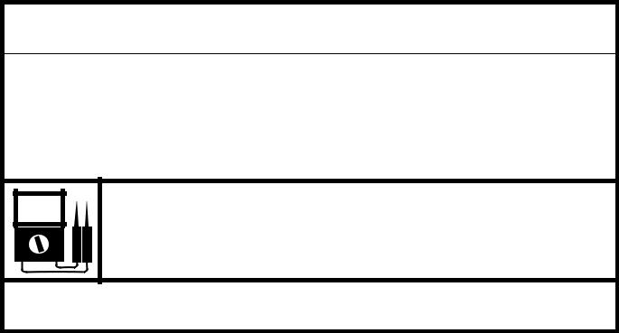
У Voltage
Connect the pocket tester (DC 20 V) to the horn coupler as shown.
|
|
|
Positive tester probe → brown 1 Negative tester probe → ground

Х Set the main switch to “ON”.
Х Measure the voltage (DC 12 V) of brown at the horn coupler.
Х Is the voltage within specification?
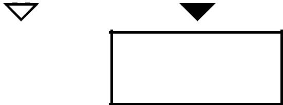
П Horn
Disconnect the horn coupler at the horn.
Connect a jumper lead 1 to the brown ter-minal in the horn coupler and the horn ter-minal.
Connect a jumper lead 2 to the horn ter-minal and ground.
Set the main switch to “ON”.
Does the horn sound?

| NO | YES | |||||||||
| The | wiring | circuit | The horn is OK. | |||||||
| from the horn coupler | ||||||||||
| to the | horn | switch | ||||||||
| coupler | and/or horn | |||||||||
| switch to ground are | ||||||||||
| faulty | and must be | |||||||||
| repaired. | ||||||||||


| YES | NO | |||
The wiring circuit from the main switch to the horn coupler is faulty and must be repaired.
8 - 42
SIGNALING SYSTEM ELEC – +
EAS00798
Р The tail/brake light fails to come on.
Tail/brake light bulb and socket
Check the tail/brake light bulb and socket for continuity.
Refer to “CHECKING THE BULBS AND
BULB SOCKETS”.
Are the tail/brake light bulb and socket OK?
| YES | NO | |||
Replace the tail/ brake light bulb, socket or both.
С Brake light switches
Check the brake light switches for continu-ity.
Refer to “CHECKING THE SWITCHES”.
Is the brake light switch OK?

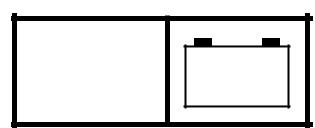
У Voltage
Connect the pocket tester (DC 20 V) to the tail/brake light assembly coupler (wire har-ness side) as shown.
Positive tester probe → green/yellow 1 Negative tester probe → black 2

Ф Set the main switch to “ON”.
Ф Pull in the brake levers.
Ф Measure the voltage (DC 12 V) of green/ yellow 1 on the tail/brake light assembly coupler (wire harness side).
Ф Is the voltage within specification?
| YES | NO | YES | NO |
| Replace the brake | This circuit is OK. | The | wiring circuit | ||||||||
| light switch(es). | from the main switch | ||||||||||
| to the | tail/brake light | ||||||||||
| assembly | coupler | is | |||||||||
| faulty | and | must | be | ||||||||
| repaired. | |||||||||||
|
|
|
8 - 43
SIGNALING SYSTEM ELEC – +
EAS00799
Ц The turn signal light, turn signal indicator light or both fail to blink.
Turn signal light bulb and socket
Check the turn signal light bulb and socket for continuity.
Refer to “CHECKING THE BULBS AND
BULB SOCKETS”.
Are the turn signal light bulb and socket OK?
| YES | NO | |||

Replace the turn sig-nal light bulb, socket or both.
• Turn signal indicator light bulb and socket
Check the turn signal indicator light bulb and socket for continuity.
Refer to “CHECKING THE BULBS AND
BULB SOCKETS”.
Are the turn signal indicator light bulb and socket OK?
| YES | NO | |||
Replace the turn sig-nal indicator light bulb, socket or both.
● Turn signal switch
• Check the turn signal switch for continuity. Refer to “CHECKING THE SWITCHES”.
• Is the turn signal switch OK?
| YES | NO | |||
Replace the left han-dlebar switch.
11. Hazard switch
• Check the hazard switch for continuity. Refer to “CHECKING THE SWITCHES”.
• Is the hazard switch OK?
| YES | NO | |||

Replace the right handlebar switch.
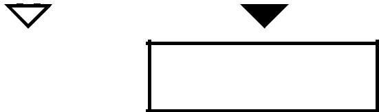
• Voltage
Connect the pocket tester (DC 20 V) to the turn signal/hazard relay coupler (wire har-ness side) as shown.
Positive tester probe → brown 1 Negative tester probe → ground

8. Set the main switch to “ON”.
9. Measure the voltage (DC 12 V) on brown 1 at the turn signal/hazard relay coupler (wire harness side).
10. Is the voltage within specification?
| YES | NO | |||
The wiring circuit from the main switch to the turn signal/ hazard relay coupler is faulty and must be repaired.
8 - 44
SIGNALING SYSTEM ELEC – +

8. Voltage
• Connect the pocket tester (DC 20 V) to the turn signal/hazard relay coupler (wire har-ness side) as shown.
Positive tester probe → brown/white 1 Negative tester probe → ground

• Set the main switch to “ON”.
• Measure the voltage (DC 12 V) on brown/ white 1 at the turn signal/hazard relay coupler (wire harness side).
• Is the voltage within specification?
| YES | NO | |||

The turn signal/haz-ard relay is faulty and must be replaced.
• Voltage
Connect the pocket tester (DC 20 V) to the turn signal light coupler, tail/brake light assembly coupler or meter assembly cou-pler (wire harness side) as shown.
|
|
|
И Front turn signal light assembly (left) Й Front turn signal light assembly (right) К Tail/brake light assembly
Л Meter assembly (turn signal indicator light)
Left turn signal light Positive tester probe →
chocolate 1 or brown/green 2 Negative tester probe → ground
Right turn signal light Positive tester probe →
dark green 3 or brown/green 4 Negative tester probe → ground
• Й
К

Л

• Set the main switch to “ON”.
• Set the turn signal switch to “  ” or “
  ”.
”.
6. Measure the voltage (DC 12 V) of the chocolate 1 or dark green 3 at the tail/ brake light assembly coupler or meter assembly coupler (wire harness side) and brown/green 2, 4 at the turn signal light coupler (wire harness side).
7. Is the voltage within specification?
| YES | NO | ||||||||
| This circuit is OK. | The | wiring | circuit | ||||||
| from | the | turn | signal | ||||||
| switch to the turn sig- | |||||||||
| nal light coupler, tail/ | |||||||||
| brake light assembly | |||||||||
| coupler | or | meter | |||||||
| assembly | coupler | is | |||||||
| faulty | and must | be | |||||||
| repaired. | |||||||||


8 - 45
SIGNALING SYSTEM ELEC – +
• The V-belt replacement indicator fails to come on.
V-belt replacement indicator bulb and socket
Check the V-belt replacement indicator bulb and socket for continuity.
Are the V-belt replacement indicator bulb and socket OK?
| YES | NO | |||
Replace the V-belt replacement indica-tor bulb, socket or both.
2. V-belt replacement indicator reset coupler
• Connect the pocket tester (Ω Ч 1) to the V-
belt replacement indicator reset coupler as
7. Voltage
• Connect the pocket tester (DC 20 V) to the meter assembly coupler (wire harness side) as shown.
Positive tester probe → light green 1 Negative tester probe → ground

• Set the main switch to “ON”.
• Measure the voltage (12 V) of light green 1 at the meter assembly coupler.
• Is the voltage within specification?
shown.
• Check the V-belt replacement indicator
reset coupler for continuity.
Positive tester probe → black 1 Negative tester probe → black 2

YES

Replace the meter assembly.
NO
The wiring circuit from the V-belt replacement indica-tor reset coupler to the meter assembly coupler (wire harness side) is faulty and must be repaired.
8.Is the V-belt replacement indicator reset coupler OK?
| YES | NO | |||

|
|
|
Replace the V-belt replacement indica-tor reset coupler.
8 - 46
SIGNALING SYSTEM ELEC – +
EAS00803 EAS00804
8. The engine oil change indicator fails to come on.
• Engine oil change indicator bulb and socket
Check the engine oil change indicator bulb and socket for continuity.
Refer to “CHECKING THE BULBS AND
BULB SOCKETS”.
Are the engine oil change indicator bulb and socket OK?
| YES | NO | |||

Replace the meter Replace the engine assembly. oil change indicator
bulb, socket or both.
10. The engine trouble warning light fails to come on.
• Engine trouble warning light bulb and socket
Check the engine trouble warning light bulb and socket for continuity.
Refer to “CHECKING THE BULBS AND
BULB SOCKETS”.
Are the engine trouble warning light bulb and socket OK?
| YES | NO | |||
Replace the meter Replace the engine assembly. trouble warning light
bulb, socket or both.
i. The fuel meter fails to come on.
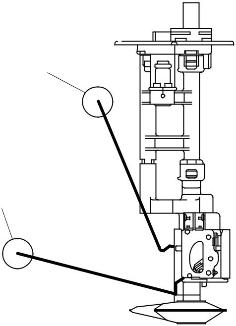
Fuel sender
Drain the fuel from the fuel tank and then remove the fuel pump (fuel sender) from the fuel tank.
Connect the fuel pump coupler to the fuel pump.
Connect the pocket tester to the fuel pump coupler (wire harness side) as shown.

Positive tester probe → green 1 Negative tester probe → black 2
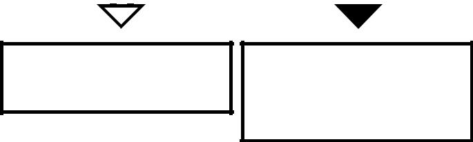
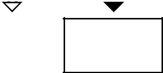
• Measure the fuel sender resistances.
Fuel sender resistance (up posi-tion “F” И )
( Ω Ч 1)
19 ~ 21 Ω at 20 °C (68 °F)
Fuel sender resistance (down position “E” Й )
( Ω Ч 10)
137 ~ 143 Ω at 20 °C (68 °F)
B B
G R / L
И
Й
• Is the fuel sender OK?
| YES | NO | |||
Replace the fuel pump.
8 - 47
SIGNALING SYSTEM ELEC – +
• Voltage
Connect the pocket tester (DC 20 V) to the meter assembly coupler (wire harness side) as shown.
Positive tester probe → green 1 Negative tester probe → black/white 2

g. Set the main switch to “ON”.
h. Measure the voltage (DC 12 V) of green 1 on the meter assembly coupler (wire har-ness side).
i. Is the voltage within specification?
| YES | NO | |||
Check the wiring connections of the entire signaling sys-tem.
• Fuel meter
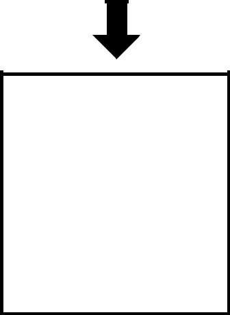
Set the main switch to “ON”.
Move the float up 1 or down 2.
Check that the fuel meter appear to “E” or
“F”.
• Does the fuel meter appear appropriately?
| YES | NO | |||||
| This circuit is OK. | Replace the meter | |||||
| assembly. | ||||||

8 - 48
SIGNALING SYSTEM ELEC – +
EAS00806
• The speedometer fails to operate.
Speed sensor
Connect the pocket tester (DC 20 V) to the speed sensor coupler (wire harness side) as shown.
Positive tester probe → white 1 Negative tester probe → black/blue 2

11. Set the main switch to “ON”.
12. Start the engine.
13. Elevate the front wheel and slowly rotate it.
14. Measure the voltage (DC 5 V) of white and black/blue. With each full rotation of the front wheel, the voltage reading should cycle from 0.6 V to 4.8 V to 0.6 V to 4.8 V.
15. Does the voltage reading cycle correctly?
| YES | NO | |||
d. Voltage
Connect the pocket tester (DC 20 V) to the meter assembly coupler (wire harness side) as shown.
|
|
|
Positive tester probe → yellow/blue 1 Negative tester probe → black/white 2

• Set the main switch to “ON”.
• Measure the voltage (DC 5 V) yellow/blue 1 on the meter assembly coupler (wire harness side).
• Is the voltage within specification?
| YES | NO | |||||
| This circuit is OK. | Replace the meter | |||||
| assembly. | ||||||

Replace the speed sensor.
8 - 49
| 8 - 50 |
| diator | |||||||||||||||||||||||||||||||||||||||||||||||||||||
| nition | |||||||||||||||||||||||||||||||||||||||||||||||||||||
| † | ў | g | fanL | motor fuse | DIAGRAMCIRCUIT | SYSTEMCOOLING | EAS00807 | SYSTEMCOOLING | |||||||||||||||||||||||||||||||||||||||||||||
| D RdL | |||||||||||||||||||||||||||||||||||||||||||||||||||||
| L/W Y/L Y/G Gy/G W B/Y B/W Y/B L | R/W R/B O | A | |||||||||||||||||||||||||||||||||||||||||||||||||||
| B/Y | Lg G/R Br/W P/W Y B/L L/Y Y/R W/Y R/L G/B B | ||||||||||||||||||||||||||||||||||||||||||||||||||||
| B/L | Br | Br | |||||||||||||||||||||||||||||||||||||||||||||||||||
| B/Y B/L | Gy B | U | Y/B | Y/B | |||||||||||||||||||||||||||||||||||||||||||||||||
| R/B | |||||||||||||||||||||||||||||||||||||||||||||||||||||
| W | W | GRIP WARMER | |||||||||||||||||||||||||||||||||||||||||||||||||||
| W | W | R | B/Y | O | O | V | WIRE HARNESS | SUB-WIRE HARNESS | |||||||||||||||||||||||||||||||||||||||||||||
| W | W | W | |||||||||||||||||||||||||||||||||||||||||||||||||||
| G/R B/L | B | ||||||||||||||||||||||||||||||||||||||||||||||||||||
| W W W | W W W | B | B/L | G/R | |||||||||||||||||||||||||||||||||||||||||||||||||
| B | R | G/Y | R/L | (GREEN) | |||||||||||||||||||||||||||||||||||||||||||||||||
| W | W W | R/B | R/B | B | Br/L | Br/L | |||||||||||||||||||||||||||||||||||||||||||||||
| R | R | Lg G/Y | G/R | B | Y/B | ||||||||||||||||||||||||||||||||||||||||||||||||
| R | R | R | R/B G/Y | ||||||||||||||||||||||||||||||||||||||||||||||||||
| B/W B R/G | R/G BB | R | R | (BLUE) | K L | X | |||||||||||||||||||||||||||||||||||||||||||||||
| Y/L G/L R/W | R/W Lg | Y/L | L/R | Br/R | ON | L/W | B | R/L | B/L | Br/W | Br/W B/L | WIRE HARNESS | DC TERMINAL | ||||||||||||||||||||||||||||||||||||||||
| R/L | SUB-WIRE HARNESS | ||||||||||||||||||||||||||||||||||||||||||||||||||||
| R/G R/W Y/L | R | R | OFF | F | G (BLACK) | R/B | L/Y | (GREEN) | |||||||||||||||||||||||||||||||||||||||||||||
| P | G/Y Lg | R/L L/Y | Br/W | C | |||||||||||||||||||||||||||||||||||||||||||||||||
| G/LB B/W | Br/L | Br/L | H | L/W | L/Y | ||||||||||||||||||||||||||||||||||||||||||||||||
| L/W | P/W | ||||||||||||||||||||||||||||||||||||||||||||||||||||
| B | &nb
Воспользуйтесь поиском по сайту:  ©2015 - 2026 megalektsii.ru Все авторские права принадлежат авторам лекционных материалов. Обратная связь с нами...
|