 |


Checking the immobilizer system
|
|
|
|
1. The immobilizer system indicator light does not come on.
1. Voltage
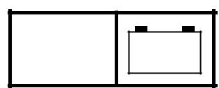
• Connect the pocket tester (DC 20 V) to the immobilizer unit coupler as shown.

Positive tester probe →
red/white 1 or red/green 2 Negative tester probe → black/white 3
• Turn the main switch to “ON”.
• Measure the voltage (DC 12 V) on the immobilizer unit coupler (wire harness side).
• Is the voltage within specification?
| YES | NO | |||

The wiring circuit from the main switch to the immobilizer unit coupler is faulty and must be repaired.
2. Wiring
• Disconnect the meter assembly coupler and immobilizer unit coupler.
• Check the immobilizer system indicator light lead (green/blue) continuity.
(meter assembly coupler – immobilizer unit coupler).
• Is the immobilizer system indicator light lead OK?
| YES | NO | |||||||
| Replace the main | The | wiring | circuit | |||||
| switch/immobilizer | from | the | meter | |||||
| unit. | assembly to immobi- | |||||||
| lizer unit is faulty and | ||||||||
| must be repaired. | ||||||||


8 - 62
 IMMOBILIZER SYSTEM ELEC – +
2. No malfunction code is displayed on the LCD display of the meter assembly.
1. Voltage
• Connect the pocket tester (DC 20 V) to the meter assembly coupler as shown.

LCD display
Positive tester probe →
red/white 1 or red/green 2 Negative tester probe → black/white 3
• Turn the main switch to “ON”.
• Measure the voltage (DC 12 V) at the meter assembly coupler (wire harness side).
• Is the voltage within specification?
| YES | NO | |||

Replace the meter The wiring circuit assembly. from the main switch to the meter assem-bly coupler is faulty and must be
repaired.
8 - 63
IMMOBILIZER SYSTEM ELEC – +
3. When the main switch is turned to “ON”, the immobilizer system indicator light flashes.
• Check if a metal object or other immobilizer system keys are placed near the immobilizer unit. If so, remove the object or keys, and then check the condition again.
| Turn the main switch to “ON” with | |||||
| another registered standard key and | Correct | ||||
| First standard key (transponder) is | |||||
| check the immobilizer system indicator | |||||
| light. The indicator light goes on for | defective. | ||||
| about 1 second, then goes off. | |||||
| Malfunction | |||||


|
|
|
Turn the main switch to “ON” with the code re-registering key and check the immobilizer system indicator light.
Malfunction
Check if a malfunction code is dis-played.
Not displayed
Immobilizer unit or ECU (engine) mal-function
Check the signal lead (yellow/blue) between the immobilizer unit and ECU (engine) connector.
Correct
| Correct | Second | standard | Re-register | ||||||
| key | (transpon- | thestan- | |||||||
| der) is defective. | dard key. | ||||||||
| Malfunc- | |||||||||
| tion | |||||||||
| Replace the | |||||||||
| standard | |||||||||
| key. | |||||||||
| Displayed | |||||||||
| Read the malfunction code and check | |||||||||
| the corresponding part. | |||||||||
| Refer to “SELF-DIAGNOSIS MAL- | |||||||||
| FUNCTION CODES”. | |||||||||


| Malfunction | Yellow/blue lead is disconnected or | |
| short-circuited. Repair or replace the | ||
| circuit. | ||
Replace the immobilizer unit.
8 - 64
| ELEC | |||||||||||||||||||
| IMMOBILIZER SYSTEM | –+ | ||||||||||||||||||
| PART REPLACEMENT KEY REGISTRATION REQUIREMENTS | |||||||||||||||||||
| Parts to be replaced | |||||||||||||||||||
| Required key | |||||||||||||||||||
| Main | Standard | ECU | Accessory | ||||||||||||||||
| lock*2 and | registration | ||||||||||||||||||
| Immobilizer | |||||||||||||||||||
| switch | key | (engine) | |||||||||||||||||
| unit | key | ||||||||||||||||||
| Standard key is lost | New standard key | ||||||||||||||||||
| All keys have been lost | *1 | Code re-registering | |||||||||||||||||
| (including code re-reg- | |||||||||||||||||||
| key and standard keys | |||||||||||||||||||
| istering key) | |||||||||||||||||||
| ECU (engine) is defec- | Code re-registering | ||||||||||||||||||
| tive | key and standard keys | ||||||||||||||||||
| Immobilizer unit is | Code re-registering | ||||||||||||||||||
| defective | key and standard keys | ||||||||||||||||||
| Main switch is defective | *1 | Code re-registering | |||||||||||||||||
| key and standard keys | |||||||||||||||||||
| Accessory lock*2 is | Not required | ||||||||||||||||||
| defective | |||||||||||||||||||
| *1 | Replace as a set with the main switch. | ||||||||||||||||||
| *2 | Accessory locks include the fuel tank cap lock and storage compartment lock. |


|
|
|
|
|
|
NOTE:

If the ECU (engine) or the immobilizer unit is replaced, both the code re-registering key and the standard keys need to be registered with the new unit(s).

8 - 65

SHTGTRBL 9
| TRBL | ||||
| SHTG | ||||
| CHAPTER 9 | ||||
| TROUBLESHOOTING | ||||
| STARTING FAILURE/HARD STARTING....................................................... | 9-1 | |||
| ENGINE..................................................................................................... | 9-1 | |||
| FUEL SYSTEM.......................................................................................... | 9-1 | |||
| ELECTRICAL SYSTEMS.......................................................................... | 9-1 | |||
| INCORRECT ENGINE IDLING SPEED........................................................... | 9-2 | |||
| ENGINE..................................................................................................... | 9-2 | |||
| FUEL SYSTEM.......................................................................................... | 9-2 | |||
| ELECTRICAL SYSTEMS.......................................................................... | 9-2 | |||
| POOR MEDIUM-AND-HIGH-SPEED PERFORMANCE................................. | 9-2 | |||
| ENGINE..................................................................................................... | 9-2 | |||
| FUEL SYSTEM.......................................................................................... | 9-2 | |||
| FAULTY CLUTCH........................................................................................... | 9-2 | |||
| ENGINE OPERATES BUT SCOOTER WILL NOT MOVE........................ | 9-2 | |||
| CLUTCH SLIPS......................................................................................... | 9-2 | |||
| POOR STARTING PERFORMANCE........................................................ | 9-2 | |||
| POOR SPEED PERFORMANCE.............................................................. | 9-3 | |||
| OVERHEATING............................................................................................... | 9-3 | |||
| ENGINE..................................................................................................... | 9-3 | |||
| COOLING SYSTEM.................................................................................. | 9-3 | |||
| FUEL SYSTEM.......................................................................................... | 9-3 | |||
| CHASSIS................................................................................................... | 9-3 | |||
| ELECTRICAL SYSTEMS.......................................................................... | 9-3 | |||
| OVERCOOLING.............................................................................................. | 9-3 | |||
| COOLING SYSTEM.................................................................................. | 9-3 | |||
| POOR BRAKING PERFORMANCE................................................................ | 9-4 | |||
| FAULTY FRONT FORK LEGS........................................................................ | 9-4 | |||
| LEAKING OIL............................................................................................ | 9-4 | |||
| MALFUNCTION......................................................................................... | 9-4 |

|
|
|
UNSTABLE HANDLING.................................................................................. 9-4
| TRBL | ||||
| SHTG | ||||
| FAULTY LIGHTING OR SIGNALING SYSTEM.............................................. | ||||
| 9-5 | ||||
| HEADLIGHT DOES NOT COME ON........................................................ | 9-5 | |||
| HEADLIGHT BULB BURNT OUT.............................................................. | 9-5 | |||
| TAIL/BRAKE LIGHT DOES NOT COME ON............................................ | 9-5 | |||
| TAIL/BRAKE LIGHT BULB BURNT OUT.................................................. | 9-5 | |||
| TURN SIGNAL DOES NOT COME ON.................................................... | 9-5 | |||
| TURN SIGNAL BLINKS SLOWLY............................................................. | 9-5 | |||
| TURN SIGNAL REMAINS LIT................................................................... | 9-5 | |||
| TURN SIGNAL BLINKS QUICKLY............................................................ | 9-5 | |||
| HORN DOES NOT SOUND...................................................................... | 9-5 |
 TRBL
TRBL
STARTING FAILURE/HARD STARTING SHTG
EAS00845
TROUBLESHOOTING
NOTE:

The following guide for troubleshooting does not cover all the possible causes of trouble. It should be helpful, however, as a guide to basic troubleshooting. Refer to the relative procedure in this man-ual for checks, adjustments, and replacement of parts.

|
|
|
