 |


Do not spin the bearing with compressed air because this will damage the bearing surfaces. 8 глава
|
|
|
|
Intake camshaft
Piston cooler
Crankshaft
Oil tank
Strainer
Suction oil pump Oil pan
Strainer
2 - 30
 COOLANT FLOW DIAGRAMS SPEC
EAS00035
COOLANT FLOW DIAGRAMS
1 Coolant reservoir
N Thermostat
O Radiator
P Water pump
Q Radiator fan
R Radiator cap
S Fast idle plunger
| 2 - 31 |
CABLE ROUTING SPEC
EAS00035
CABLE ROUTING
4. Headlight sub-wire harness
5. Horn
6. Horn (H mark on the back of the horn)
• Securely fasten the wire strap to the front cowl-ing hook to prevent it from being pulled out by the headlight assembly. (left and right)
1 Connect the headlight sub-wire harness to the wire harness on top of the stay (left and right). After making the connection, push the coupler
between the front cowling and the air filter case.
• Connect the taped headlight lead coupler to the headlight’s white marked side (left side: high beam side).
(For GB the right side is the high beam side.)

2 - 32
CABLE ROUTING SPEC
9 Fasten the headlight sub-wire harness using a lead holder. (left and right)
М Connect the turn signal light. (left and right) Н Route the horn lead through the wire guide.
2) After passing the horn lead through the lead holder, crimp the lead holder.
3) Install a wire harness guide to hold down the wire harness.
• Route the throttle cables between handle under cover and upper bracket.
• Route the throttle cables through the hole of the lower handlebar cover.
4. Connect the brake light switch lead through the handlebar switch side.
У Fasten the handlebar switch lead to the handle-bar using a plastic band. The fastening location is the bend area on the bottom of the handlebar.
3. Route the left handlebar switch leads over the right handlebar switch leads.
2 - 33
CABLE ROUTING SPEC
4. Fasten the right handlebar switch leads to the handlebar with a plastic band.
6. Route the rear brake hose and left handlebar switch leads over the wire harness.
2 - 34
CABLE ROUTING SPEC
1 Rear brake hose
2 Front brake hose
3 Rear brake lock lever cable
4 Left handlebar switch
6. Route the rear brake lock lever cable in front of the handlebar, then down through the space between the handlebar and the upper bracket.
3. Fasten the wire harness by sliding the plastic holder on the wire harness onto the stud on the handlebar.
4. Fasten the grommets on the brake hoses with the holder.
|
|
|
5. Install the rear brake lock lever cable after lubri-cating the grease to the cable end.
6. Install the rear brake lock lever cable after turn-ing the parking brake lever as illustration.
• Install the cable end (Face the notch side to lever).

2 - 35
| CABLE ROUTING | SPEC | ||||
| 1 Grommet | |||||
| C Fuel tank breather hose | |||||
| 2 Fuel over flow hose | D Hose holder | ||||
| 3 Fuel tank | E Hose holder | ||||
| 4 Fuel overflow tray | F Fuel hose | ||||
| 5 Fuel tank cap | G Fuel pump lead | ||||
| 6 Upper side cover moulding (left) | H Hose guide | ||||
| 7 Hose guide | I Roll over valve assembly | ||||
| 8 Grommet | J Holder | ||||
| 9 Footrest board | K Fuel pump | ||||
| 0 Hose clamp | L Fuel pump bracket | ||||
| A Fuel tank breather hose | M Fuel hose connector cover | ||||
| B Rear footrest assembly |


| Ч | Т | |||||||||
| F | ||||||||||
| С | ||||||||||
| I | Х | |||||||||
| D-D | J | |||||||||
| Ф | E F | Х | О | C | ||||||
| DУ | ||||||||||
| E | ||||||||||
| K | ||||||||||
| Р | F | |||||||||
| 3 F | G | |||||||||
| Х E | ||||||||||
| L | П | |||||||||
| E-E | B | Х | A | |||||||
| H | ||||||||||
| MШ | F | 34 5 | A | |||||||
| B | ||||||||||
| C | Ц | |||||||||
| F-F | ||||||||||
| Й | ||||||||||
| О | 9 8 | Р | И | |||||||
| C | П | |||||||||
| Left side | ||||||||||
| DC | D | |||||||||
| B К | A 0 | |||||||||
| Л | ||||||||||
| М | Right side | |||||||||
| Н | Tighten the fuel | |||||||||
| tank comp.bolt | ||||||||||
| 2 - 36 |
CABLE ROUTING SPEC
|
|
|
• Do not protrude from the upper side cover moul-ding (left).
Й Fix the fuel overflow hose with the white paint mark as shown.
К Pass the fuel tank breather hose to the hose guide of frame (both right and left).
Л Pass the fuel tank breather hose to the hose guide of rear footrest assembly.
М Pass the fuel tank breather hose to the hose guide of frame.
Н 50 ~ 70 mm (1.97 ~ 2.76 in)

О 2 ~ 5 mm (0.08 ~ 0.20 in)
П Install the grommet to the footrest board securely.
Р Install the grommet to the fuel tank securely.
С Make sure that the clip end faces to the front side.
Т Install the grommet to the fuel tank securely after installing the hoses.
У Fasten the fuel hose and fuel pump lead with a hose holder, making sure that there are no twists in the hose or lead.
| Ч | Т | |||||||||
| F | ||||||||||
| С | ||||||||||
| I | Х | |||||||||
| D-D | J | |||||||||
| Ф | E F | Х | О | C | ||||||
| DУ | ||||||||||
| E | ||||||||||
| K | ||||||||||
| Р | F | |||||||||
| 3 F | G | |||||||||
| Х E | ||||||||||
| L | П | |||||||||
| E-E | B | Х | A | |||||||
| H | ||||||||||
| MШ | F | 34 5 | A | |||||||
| B | ||||||||||
| C | Ц | |||||||||
| F-F | ||||||||||
| Й | ||||||||||
| О | 9 8 | Р | И | |||||||
| C | П | |||||||||
| Left side | ||||||||||
| DC | D | |||||||||
| B К | A 0 | |||||||||
| Л | ||||||||||
| М | Right side | |||||||||
| Н | Tighten the fuel | |||||||||
| tank comp.bolt | ||||||||||
| 2 - 37 |
CABLE ROUTING SPEC
|
|
|
Ф Align the projection on the fuel pump with the projection on the fuel tank when installing the
fuel pump.
Х Tighten the fuel pump bolts in the proper tighten-ing sequence as shown.
Ц Pass the fuel hose to the hose guide.
Ч Pass the fuel hose to the inside of the frame guide.
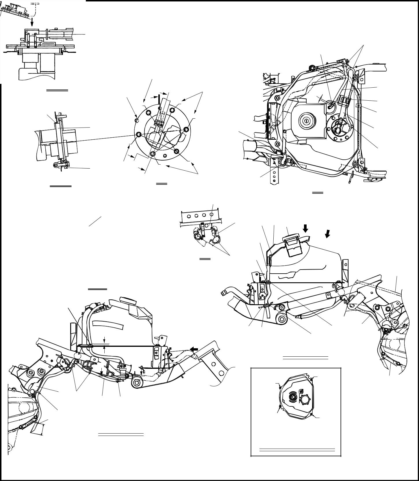
Ш After connecting the fuel hose connector to the fuel tank, install the fuel hose connector cover completely onto the connector.
Install and remove the fuel hose connector and cover manually. Do not use tools.
| Ч | Т | |||||||||
| F | ||||||||||
| С | ||||||||||
| I | Х | |||||||||
| D-D | J | |||||||||
| Ф | E F | Х | О | C | ||||||
| DУ | ||||||||||
| E | ||||||||||
| K | ||||||||||
| Р | F | |||||||||
| 3 F | G | |||||||||
| Х E | ||||||||||
| L | П | |||||||||
| E-E | B | Х | A | |||||||
| H | ||||||||||
| MШ | F | 34 5 | A | |||||||
| B | ||||||||||
| C | Ц | |||||||||
| F-F | ||||||||||
| Й | ||||||||||
| О | 9 8 | Р | И | |||||||
| C | П | |||||||||
| Left side | ||||||||||
| DC | D | |||||||||
| B К | A 0 | |||||||||
| Л | ||||||||||
| М | Right side | |||||||||
| Н | Tighten the fuel | |||||||||
| tank comp.bolt | ||||||||||
| 2 - 38 |
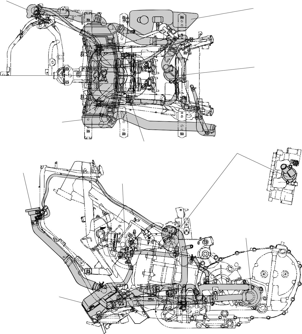
| CABLE ROUTING | SPEC | ||||
| XP500 | |||||
| 1 Main switch/immobilizer unit | A Throttle position sensor coupler | ||||
| 2 Throttle cable | B Starter motor lead | ||||
| 3 Brake hose | C Rectifier/regulator | ||||
| 4 Meter assembly | D Starting circuit cut-off relay 1 | ||||
| 5 Cooling system air bleed hose | E Turn signal/hazard relay | ||||
| 6 Horn lead | F O2 sensor | ||||
| 7 Radiator filer hose | G V-belt replacement indicator reset coupler | ||||
| 8 Ignition coil | H O2 sensor coupler | ||||
| 9 Coolant reservoir hose | I Fuel pump lead | ||||
| 0 Radiator fan motor lead | J Fuel tank breather hose |
|
|
|
|
|
|
