 |


Digital circuit tester 90890-03174
|
|
|
|
Ш Measure the throttle position sensor volt-age.
Ш Adjust the throttle position sensor angle so that the voltage is within the specified range.

Throttle position sensor voltage 0.63 ~ 0.73 V
(yellow – black/blue)
Ъ After adjusting the throttle position sensor angle, tighten the throttle position sensor
screws 3.
▲▲▲▲▲▲▲▲▲▲▲ ▲▲▲▲▲▲▲▲▲ ▲▲▲▲▲▲▲▲▲▲▲▲
7 - 30
– +
ELEC 8
 ELEC
ELEC 
 – +
– + 
CHAPTER 8
ELECTRICAL SYSTEM
| ELECTRICAL COMPONENTS........................................................................ | 8-1 |
| CHECKING SWITCH CONTINUITY................................................................ | 8-4 |
| CHECKING THE SWITCHES.......................................................................... | 8-5 |
| CHECKING THE BULBS AND BULB SOCKETS.......................................... | 8-6 |
| TYPES OF BULBS.................................................................................... | 8-6 |
| CHECKING THE CONDITION OF THE BULBS....................................... | 8-7 |
| CHECKING THE CONDITION OF THE BULB SOCKETS....................... | 8-8 |
| IGNITION SYSTEM......................................................................................... | 8-9 |
| CIRCUIT DIAGRAM.................................................................................. | 8-9 |
| TROUBLESHOOTING............................................................................ | 8-10 |
| ELECTRIC STARTING SYSTEM.................................................................. | 8-15 |
| CIRCUIT DIAGRAM (XP500).................................................................. | 8-15 |
| CIRCUIT DIAGRAM (XP500A)................................................................ | 8-16 |
| STARTING CIRCUIT CUT-OFF SYSTEM OPERATION (XP500).......... | 8-17 |
| STARTING CIRCUIT CUT-OFF SYSTEM OPERATION (XP500A)....... | 8-18 |
| TROUBLESHOOTING............................................................................ | 8-19 |
| STARTER MOTOR........................................................................................ | 8-23 |
| CHECKING THE STARTER MOTOR..................................................... | 8-25 |
| ASSEMBLING THE STARTER MOTOR................................................. | 8-27 |
| CHARGING SYSTEM.................................................................................... | 8-28 |
| CIRCUIT DIAGRAM................................................................................ | 8-28 |
| TROUBLESHOOTING............................................................................ | 8-29 |
| LIGHTING SYSTEM...................................................................................... | 8-31 |
| CIRCUIT DIAGRAM................................................................................ | 8-31 |
| TROUBLESHOOTING............................................................................ | 8-33 |
| CHECKING THE LIGHTING SYSTEM.................................................... | 8-35 |
| SIGNALING SYSTEM................................................................................... | 8-39 |
| CIRCUIT DIAGRAM................................................................................ | 8-39 |
| TROUBLESHOOTING............................................................................ | 8-41 |
| CHECKING THE SIGNALING SYSTEM................................................. | 8-42 |
| COOLING SYSTEM....................................................................................... | 8-50 |
| CIRCUIT DIAGRAM................................................................................ | 8-50 |
| TROUBLESHOOTING............................................................................ | 8-51 |
| ELEC | ||||||||||
| –+ | ||||||||||
| IMMOBILIZER SYSTEM................................................................................ | 8-54 | |||||||||
| SYSTEM DIAGRAM................................................................................ | 8-54 | |||||||||
| CIRCUIT DIAGRAM................................................................................ | 8-55 | |||||||||
| GENERAL INFORMATION..................................................................... | 8-56 | |||||||||
| KEY CODE REGISTRATION.................................................................. | 8-57 | |||||||||
| SELF-DIAGNOSIS MALFUNCTION CODES.......................................... | 8-59 | |||||||||
| TROUBLESHOOTING............................................................................ | 8-61 | |||||||||
| CHECKING THE IMMOBILIZER SYSTEM............................................. | 8-62 | |||||||||
| PART REPLACEMENT KEY REGISTRATION REQUIREMENTS | 8-65......... |
 ELECTRICAL COMPONENTS ELEC – +
|
|
|
EAS00729
ELECTRICAL SYSTEM
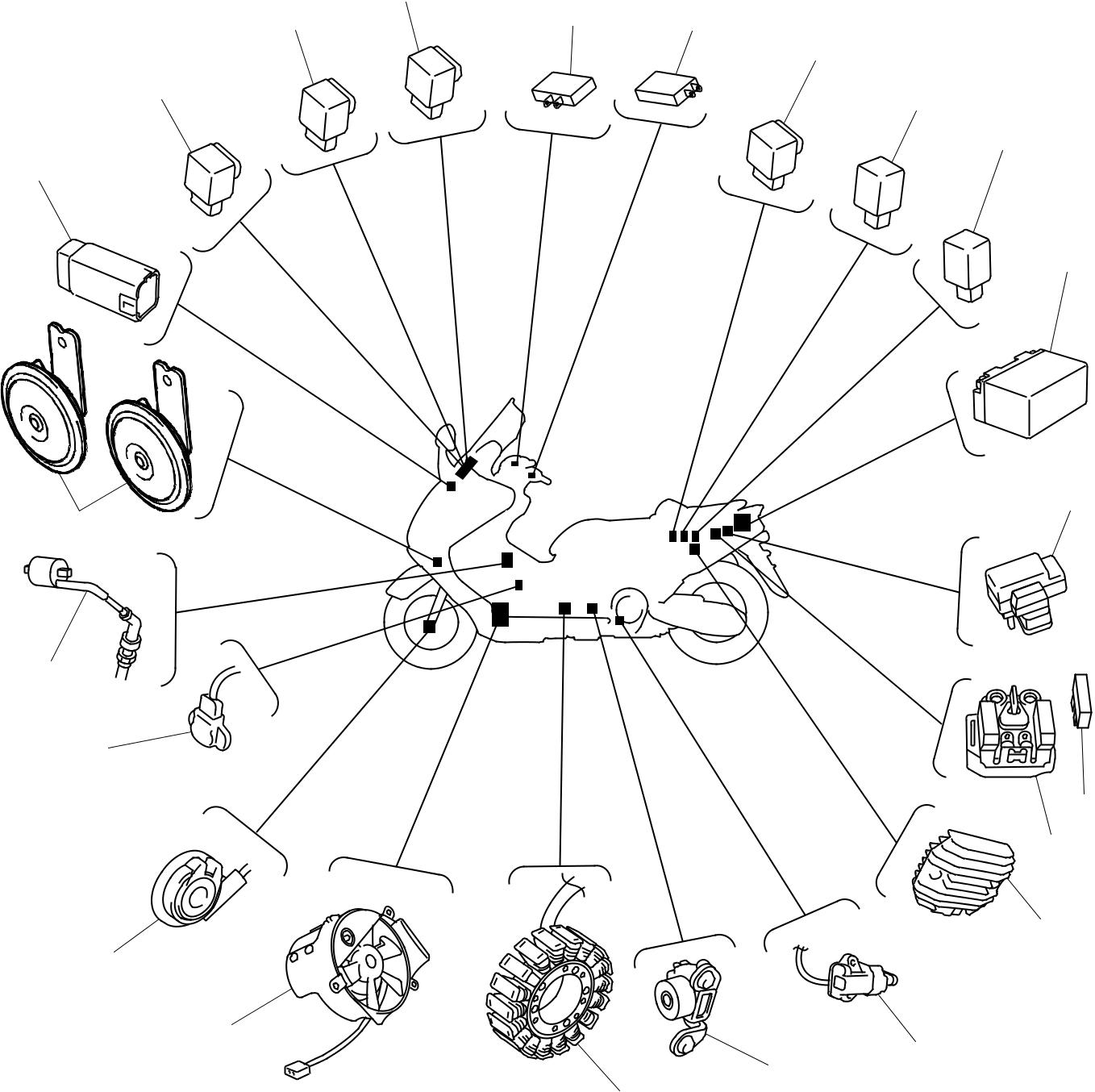
ELECTRICAL COMPONENTS
1 Front brake light switch 8 Starter relay
2 Rear brake light switch 9 Main fuse
3 Turn signal/hazard relay 0 Rectifier/regulator
4 Starting circuit cut-off relay 1 A Sidestand switch
5 Starting circuit cut-off relay 2 (XP500A) B Crankshaft position sensor
|
|
|
6 Battery C Stator coil
7 Fuse box D Radiator fan
| L | ||
| K | ||
| J | ||
| I | ||
| H | ||
| G | ||
| F | ||
| E | ||
| D | A | |
| B | ||
| C | ||
| 8 - 1 |
ELECTRICAL COMPONENTS ELEC – +
E Speed sensor (XP500)
F Throttle position sensor
G Ignition coil
Ы Horn
Ы Lean angle cut-off switch
Ы Fuel injection system relay
Ы Headlight relay
Ы Radiator fan motor relay
| L | ||
| K | ||
| J | ||
| I | ||
| H | ||
| G | ||
| F | ||
| E | ||
| D | A | |
| B | ||
| C | ||
| 8 - 2 |
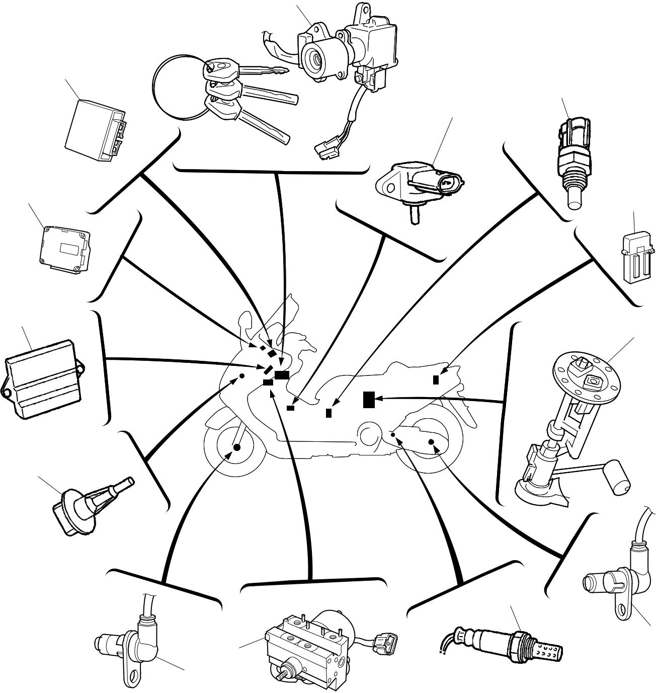
ELECTRICAL COMPONENTS ELEC – +
1 ECU (ABS) (XP500A)
21 Fail-safe relay (XP500A)
22 Main switch/immobilizer unit
23 Intake air pressure sensor
24 Coolant temperature sensor
25 ABS motor fuse
26 Fuel pump
27 Rear wheel sensor (XP500A)
28 O2 sensor
0 Hydraulic unit (XP500A)
A Front wheel sensor (XP500A)
B Intake air temperature sensor C ECU (engine)
| C | |
| B | |
| A | |
| 8 - 3 |
CHECKING SWITCH CONTINUITY ELEC – +
EAS00730
CHECKING SWITCH CONTINUITY

Check each switch for continuity with the pocket tester. If the continuity reading is incor-rect, check the wiring connections and if nec-essary, replace the switch.
CAUTION:

Never insert the tester probes into the cou-pler terminal slots 1. Always insert the probes from the opposite end of the cou-pler, taking care not to loosen or damage the leads.


Pocket tester 90890-03112, YU-03112-C
NOTE:

28 Before checking for continuity, set the pocket tester to “0” and to the “Ω Ч 1” range.
29 When checking for continuity, switch back and forth between the switch positions a few times.

The terminal connections for switches (e.g., main switch, engine stop switch) are shown in an illustration similar to the one on the left.
The switch positions a are shown in the far left column and the switch lead colors b are shown in the top row in the switch illustration.
NOTE:
“ 
 ” indicates a continuity of electricity between switch terminals (i.e., a closed circuit at the respective switch position).
The example illustration on the left shows that:
There is continuity between red, brown/blue, and brown/red when the switch is set to “ON”. There is continuity between red and brown/red when the switch is set to “  ”.
”.
8 - 4
CHECKING THE SWITCHES ELEC  – +
– +
EAS00731
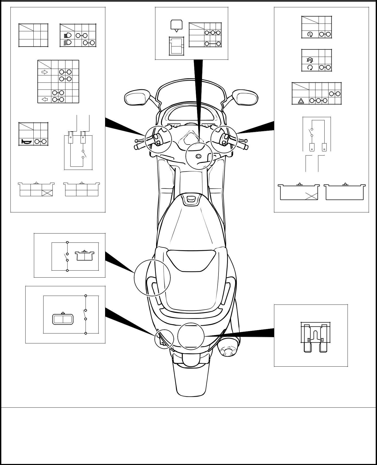
CHECKING THE SWITCHES
Check each switch for damage or wear, proper connections, and also for continuity between the ter-minals. Refer to “CHECKING SWITCH CONTINUITY”.
Damage/wear → Repair or replace. Improperly connected → Properly connect.
Incorrect continuity reading → Replace the switch.
|
|
|
U 2
| R/Y Y | Y L/B G | |
–
PASS 
Ch Br / W Dg
NR
N
| Br/R | R Br/L Br/R |
ON
OFF
R P
Br / L
A
L / W B
–
 R / W R / B
Ch Br / WDg L / Y Br / L
NL
4 5 B / Y L / Y
P B
–
| Br/W P B | Y G L/Y | |||||
| L/B R/Y | Dg Ch B/Y |
(BLUE)
B B
(BLUE)
R L / G
•
B
| Br G/Y | |||||||||||
| Dg | Br/W | Ch | G/Y | R/B | R/W | ||||||
| Br/L | L/Y | L/W | B | Br | |||||||
| (BLACK) | (BROWN) |
C
| 1 Pass switch | 6 Sidestand switch | A Hazard switch |
| 2 Dimmer switch | 7 Storage box light switch | B Front brake light switch |
| 3 Turn signal switch | 8 Main switch | C Fuse |
| 4 Horn switch | 9 Start switch | |
| 5 Rear brake light switch | 0 Engine stop switch |
8 - 5
CHECKING THE BULBS AND BULB SOCKETS ELEC – +
EAS00733
CHECKING THE BULBS AND
BULB SOCKETS
Check each bulb and bulb socket for damage or wear, proper connections, and also for con-tinuity between the terminals.
Damage/wear → Repair or replace the bulb, bulb socket or both.
Improperly connected → Properly connect. No continuity → Repair or replace the bulb, bulb socket or both.
TYPES OF BULBS

The bulbs used on this scooter are shown in the illustration on the left.
FF Bulbs A and B are used for the headlights and usually use a bulb holder that must be detached before removing the bulb. The majority of these types of bulbs can be removed from their respective socket by turning them counterclockwise.
GG Bulbs C is used for turn signal and tail/ brake lights and can be removed from the socket by pushing and turning the bulb counterclockwise.
HH Bulbs D and E are used for meter and indi-cator lights and can be removed from their respective socket by carefully pulling them out.

8 - 6
CHECKING THE BULBS AND BULB SOCKETS ELEC – +
|
|
|
